# Welcome to CrownCAD 2024 R4
CrownCAD 2024 R4, widely absorb the most authentic feedback from users, to maximize the realization of customer needs. In terms of ease of use, it is committed to improving customer experience; In terms of functionality, continuously adding commands that customers urgently need can help you quickly complete product design and development work.
Major enhancements:
| Sketches | Add arc length annotations. |
| Added virtual intersection function. | |
| Added quadrant points to capture circles/arcs. | |
| Added equality constraint in 3D sketch. | |
| New positioning sketch function, support for custom sketch origin and orientation. | |
| Offset supports symmetrical offset to both sides at the same time, offset circle supports adding offset distance size. | |
| New sketch library function, you can save the sketch as a whole in the library, subsequent repeated calls. | |
| Parts and Features | Stretch supports more depth types, and stretch excision supports reverse lateral excision. |
| Hole support Create slot holes, support more depth types, ease of use optimization. | |
| Transform supports multiple choice geometry, support transform grid. | |
| Datum surface support drag and drop fast creation. | |
| Datum new by point to create a specified face normal way. | |
| Added the function of parent-child relationship table to quickly view the feature association relationship. | |
| Import and export data from 3D curves through XYZ points supports common use with SOLIDWORKS data. | |
| Support for creating vortex lines. | |
| Assembly | Fit new width fit, hinge fit. |
| New view fit function to quickly view the fit of a specified instance. | |
| Replacement parts or assemblies can specify replacement instances and reattach fit relationships. | |
| Add the parent-child relationship command to quickly view the feature association relationship. | |
| New instance grouping function, classified management of component instances, coordination, etc. | |
| Drawing | Section view thread effect optimization. |
| Added the move out profile command, simple and intuitive representation of a small part of the large model pipe and similar areas. | |
| Model view supports viewing angles defined in 3D. | |
| Support to set the first view, the third view projection type. | |
| Added the Rotate view command to rotate the view on the plane. | |
| Decorate thread line annotation and display effect optimization. | |
| New automatic dimensioning function, automatically generate the size of the specified style. | |
| The size supports the maximum and minimum size of the circle/arc, optimizes the display effect of the size boundary line, and supports the adjustment of the end position of the size boundary line. | |
| New virtual intersection command, support to create, mark the virtual intersection between the lines. | |
| Annotations support record the last set of parameters. | |
| Hole marking can identify the number of holes with the same feature, and the depth of thread through is no longer marked according to GB requirements. | |
| Note can set the rotation Angle, support the association of custom attributes. | |
| Roughness default direction optimization, adding the option to quickly adjust the direction. | |
| Form and position tolerances support merging with dimensions, automatically adding extension lines beyond the marked range, and automatically capturing horizontal vertical angles. | |
| Automatic part serial number supports sorting and designating the first part. | |
| Annotations support drag and drop to toggle associated elements and generate multiple arrows as one-to-many annotations. | |
| Add arrowhead style for annotations. | |
| Area Fill/Section line supports custom fill model plane areas. | |
| Local view parent view label supports drag and drop to modify the position. | |
| The material list supports modification of part order and serial number. | |
| Support one click to display and hide the sketch projected in the parts. | |
| New layer function, batch management annotation and sketch style. | |
| Added the ability to show and hide annotations, so that annotations can be displayed and hidden individually. | |
| When deleting a model view, keep subviews of its projection view type. | |
| Evaluation Tools | |
| Measurement support set parameters such as accuracy, can display XYZ dimensions, support measurement grid. | |
| New quick measurement function, the lower right corner of the viewport displays the basic parameters of the element. | |
| New thickness analysis command, which can identify thin and thick areas of parts, determine different thicknesses of parts, and assist designers in evaluating product structure. | |
| New zebra stripe command, used to identify and check the details in the surface, such as the continuity of the surface, whether there are defects, for surface quality assessment. | |
| New draw analysis command for visually evaluating whether the model has sufficient draw Angle and can be removed from the mold during production. | |
| Sheet Metal | |
| Added molding tool command to save reused stamped entities. | |
| Matrix flanges support closed contours with holes. | |
| Flange multiple selection adjacent edges automatically add miter, tear shape release slot can be selected specific style. | |
| Miter flange corner molding effect optimization, support complex continuous side lines. | |
| Conversion to sheet metal support picks up rounded corners as bending surfaces to correctly convert existing sheet metal models. | |
| Stamping and forming features support mirror image and array. | |
| Data conversion | Support for importing Creo engineering drawings. |
| Optimized Cgr, rhino, 3dxml file import effect. | |
| Support for importing SOLIDWORKS custom properties. | |
| Support for importing space points. | |
| Add the datum surface implicit, grid import mode Settings. | |
| Collaboration | New document sharing feature to share individual documents. |
| New template sharing function, which can share document templates and custom attribute templates. | |
| System Settings | Document properties add trailing zeros, size boundaries, rounding decimals, and unit system options. |
| Apply | Support for setting the single increment value of the size increase or decrease button. |
| Support to cancel the account, support to change the mobile phone number. | |
| Support double-click middle key adaptive. | |
| Render | Add grid rendering. |
| Added perspective camera to view models with perspective effects. | |
| Library/Templates | Add bearings to standard parts library. |
| Universal | Comprehensive update of variable management, increase function expression, optimize interaction. |
| Features support grouping. | |
| When copying documents, you can choose whether to copy the associated documents synchronously. | |
| Supports automatically judging and picking points on the line according to the picked position. | |
| Animations | Supports editing the position of parts in existing keyframes. |
# Sketches
# Dimensions
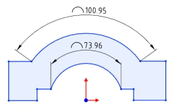
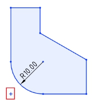
# Arc length annotations
Supports the creation of arc length annotations in sketches, and can be used as drive or driven dimensions.
Creation steps:
1) Click the [Label Arc Length] command in the Size Constraints drop-down menu.
2) Click the left button to select the arc edge line to display the arc size preview.
3) Click the left button again after moving the mouse to place the arc dimensions.
4) Continue to select other arcs that you want to label for continuous labeling.
5) Click the "Close" button to end the annotation.
Note:Only circular arc lines can be annotated.
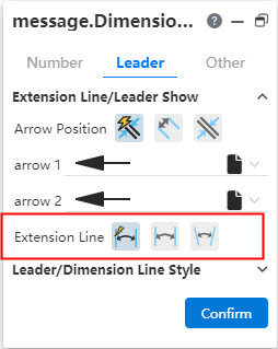
Label style:The size boundary style can be modified as shown in the following figure.
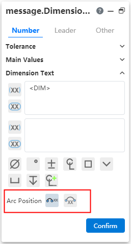
Arc symbol position:The arc length marked arc symbol position can be modified as shown in the following picture.
Note:When the radius and arc length are set at the same time, if the arc length value set is too large, resulting in the arc Angle x exceeding 360°, the actual arc Angle T= X-n *360, n is the maximum integer value when T is positive.
# Dimension boundary line optimization
The boundary line style of the dimensions is optimized to avoid dimensioning Angle dimensions that are out of the current window range.
Default style:The size boundary parameters can be set in System Settings - Document Properties - Dimensions.
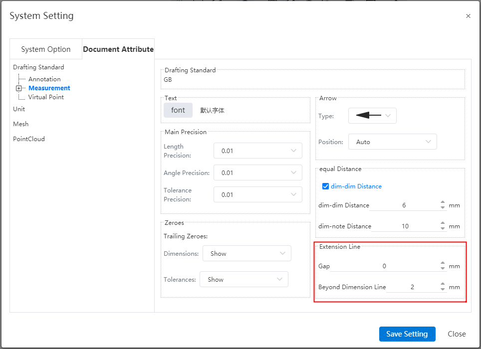
Gap:The gap between the size boundary line and the annotated element.
Beyond the size line length:The length of the size boundary line beyond the size line.
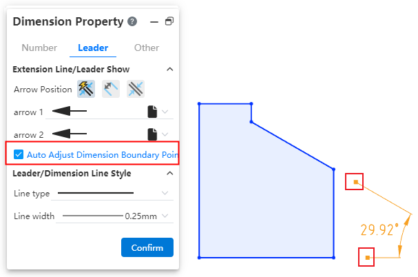
Manual adjustment:Select the Angle or length size, uncheck "Automatically adjust the size boundary end point" in the lead Tab of the size property dialog box, the square control mark is displayed at the end of the size boundary line, you can manually drag the control mark to adjust the boundary line. Check it again to restore the automatic adjustment of the boundary line.
# Virtual intersections
You can create virtual intersections where the extension lines of disjoint elements intersect for easy positioning during subsequent processing.
How to create:
- Method 1:Pre-pick element creation
1)Select two lines by holding down ctrl or by box picking, etc.
2)Click the "Draw Points" command or the "Virtual Intersection" command to generate virtual intersections.
- Method 2:Create using the Virtual intersection command
1)Click the Virtual Intersection command in the Draw Points drop-down box.
2)Select two lines.
3)Click the OK or Apply button to generate virtual intersections.
- Method 3:Create when dimensioning
1)Use the commands for dimensioning with size constraints.
2)Normal dimensioning.
3)Right click on element A where virtual intersections can be created.
4)Click Find Intersections.
5)Click another element B to generate A virtual intersection of A and B.
6)Continue annotating.
Elements that create virtual intersections:
Sketch lines, model edges, support to select the same/different types of lines to create virtual intersections
Straight lines, curves can be created on the extension line virtual intersection points.
When the selected line has multiple intersections, create the virtual intersections closest to the mouse click.
In the sketch, it is supported to pick up elements outside the sketch to create virtual intersections.
The use of virtual intersection points:
Analog sketch drawing points.
Supports adding dimensions, geometric constraints.
Measurements can be made.
Can be picked up in the feature dialog box, such as stretch boss feature picking points as directions, etc.
Special case:
Cannot be picked up as an outline in the lofting boss feature.
Sketch array and scale primitives The elements to be array/scaled do not support virtual intersections, scaled primitives' scale points support virtual intersections.
Virtual intersections Style:The display style of virtual intersections can be modified in "System Settings - Document Properties - Virtual intersections".
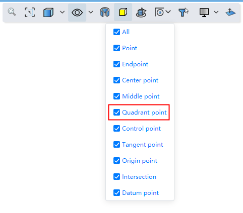
# Quadrant Points
Supports capturing quadrant points of circle/arc lines.
Start the drawing class command, the viewport displays the quadrant of the circle/arc line, which can be captured for drawing.
You can control whether to capture quadrantal points through the "Capture" function of the toolbar of the leading view.
# Mirroring
The mirror supports the selection of coordinate axes, which makes it easy to quickly create images that mirror relative coordinate values.
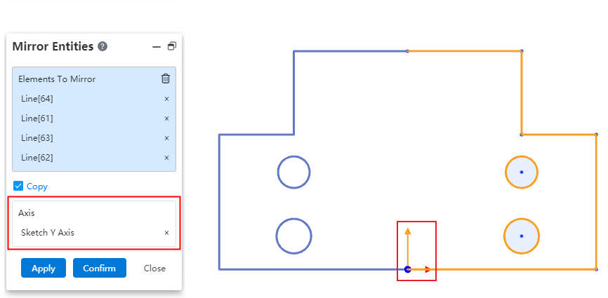
When using the mirror command, directly pick up the XY axis from the origin of the sketch in the viewport as the mirror axis to view the preview and create the graph.
# Add constraints to the center of the circle
The Add constraint command supports picking up the center of a solid surface circle edge without having to convert the boundary to generate a circle before picking up the center.
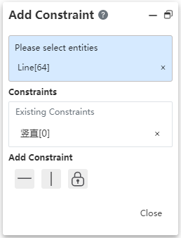
After opening the "Add constraint" command, the center of the circle is displayed after a short pause when the mouse points to the circular edge.
# 3D Sketch
# Equality constraint
Support to add equal constraints in 3D sketches, which is easy to draw sketches such as equal length solder paths.
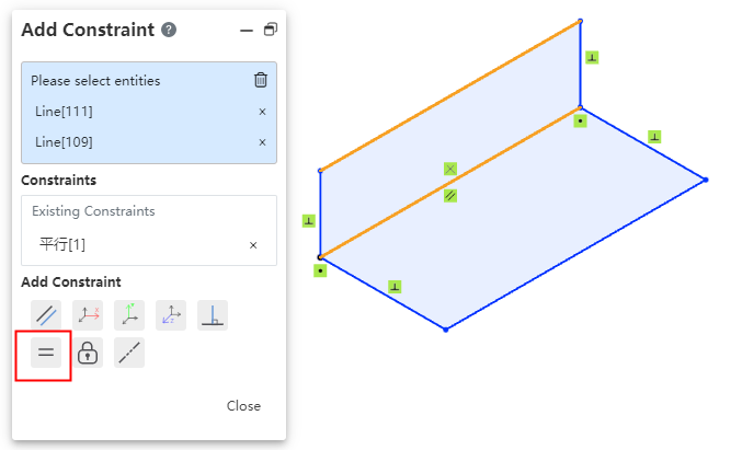
Choose two or more straight lines so that the lines remain equal in length.
Choose two or more circles/arcs so that the circle radii remain equal.
# Positioning sketch
Support for creating custom origin and XY orientation positioning sketches. You can choose the corresponding coordinate system or point as the center of the current sketch, which can reduce the drawing of many auxiliary lines and improve the design efficiency.
Creation method:
1)Click the Draw Sketch button.
2)Select the sketch plane and set the sketch origin and orientation as desired.
3)Click OK to generate the sketch.
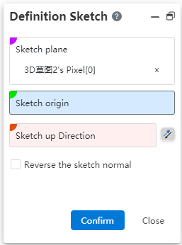
Dialog box control description:
Sketch plane: Required, single option. The plane surface of the datum, sketch/entity can be picked up.
Sketch origin: Optional, single option. Pickable points, points can be from sketch, solid, surface, curve, reference element.
Direction up the sketch: Optional. Line or two points can be picked up. Click the reverse button to reverse.
Reverse sketch normal: This button is not checked by default. After it is checked, the sketch normal direction is reversed.
# Offset
# Bilateral symmetry
Support bilateral symmetry, improve design efficiency, can offset two lines at a time.
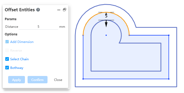
Usage:Check the "bidirectional" option in the offset dialog box to generate the offset line with bilateral symmetry.
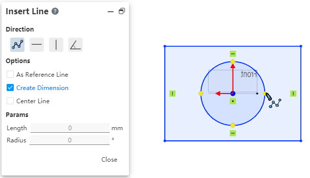
# Offset circle adds constraint
Add constraints and offset distance dimensions after offset circle/arc.
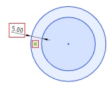
Removing the constraint cancels the offset effect between the two circles.
Modify Offset distance Dimension value To change the offset distance.
Use the Size Constraint command to add offset dimensions between concentric circles.
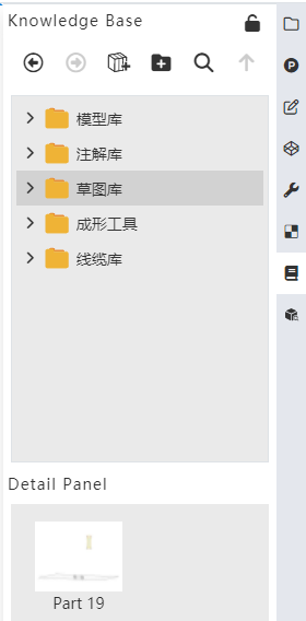
# Sketch Gallery
The 2D sketches in the parts can be saved to the knowledge base for quick follow-up calls and improved design efficiency.
# Add to library
Method 1:
1)Right-click sketch in feature list and click [Add to Knowledge Base].
2)Set the name and storage location in the Add to Knowledge Base dialog box.
3)Click OK to finish adding.
Method 2:
1)Open the knowledge base and click Add to Library.
2)Pick up the sketch in the feature list or viewport.
3)Set the name and storage location in the Add to Knowledge Base dialog box.
4)Click OK to finish adding.
Note 1:After the sketch is stored in the library, the internal constraints of the sketch remain, and the external constraints are automatically deleted. For example: the horizontal constraints of the line are retained, and the isometric constraints of the line and the external line are deleted.
Note 2:The sketch entered into the library is disconnected from the source sketch, and any modifications made by the source sketch do not affect the sketch in the library.
# Call sketch
Method 1:
1)In the Sketch Gallery Details panel, select Sketch and right click the [Insert] button.
2)Set the sketch location in the Locate Sketch dialog box and click OK to enter the sketch.
3)To display the preview in the sketch, select the location you want to place according to the preview by clicking the left mouse button.
4)Multiple identical elements can be generated by left-clicking in different locations.
5)Exit the sketch.
Method 2:
1)Select sketch from Knowledge Base in document, drag to viewport and release left mouse button.
2)Set the sketch location in the Locate Sketch dialog box and click OK to enter the sketch.
3)To display the preview in the sketch, select the location you want to place according to the preview by clicking the left mouse button.
4)Multiple identical elements can be generated by left-clicking in different locations.
5)Exit the sketch.
Method 3:
1)Create and go into a sketch.
2)Select the sketch from the Knowledge Base in the document, right click the Insert button, or drag into the viewport to release the left mouse button.
3)To display the preview in the sketch, select the place to place according to the preview and click the left mouse button.
4)Multiple identical elements can be generated by left-clicking in different locations.
5)Exit the sketch.
# Manage Sketches
Right-click the sketch you want to manage in the sketch gallery to "Delete, rename, edit".
# Features
# Stretch boss/cut
# To the distance from the specified face
The stretching method can be selected [distance from the specified face]. This option can be used when you need to maintain a certain gap with a face or interference.
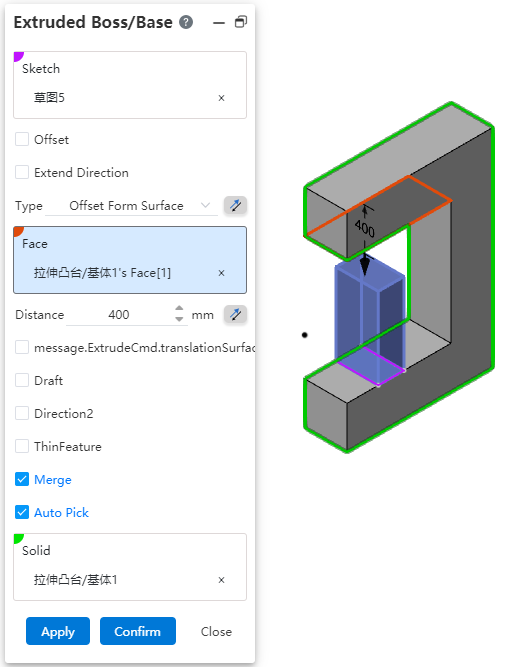
Dialog box control description:
Method:You can select "distance from the specified surface", click the back button to change the stretching direction.
Face:Select the specified face.
Distance:Set the offset distance, support the input range [0.001,10000000], support variables, equations. Click the reverse button in the back to modify the offset direction.
Translation surface:Translation surface effect when checked, equidistant surface effect when unchecked.
Other parameters:Consistent with other stretching methods.
# Shape to a point
The stretching method can be selected [shape to a point]. This option can be used when there is no surface at the point to which you want to stretch and you cannot select a specified depth.
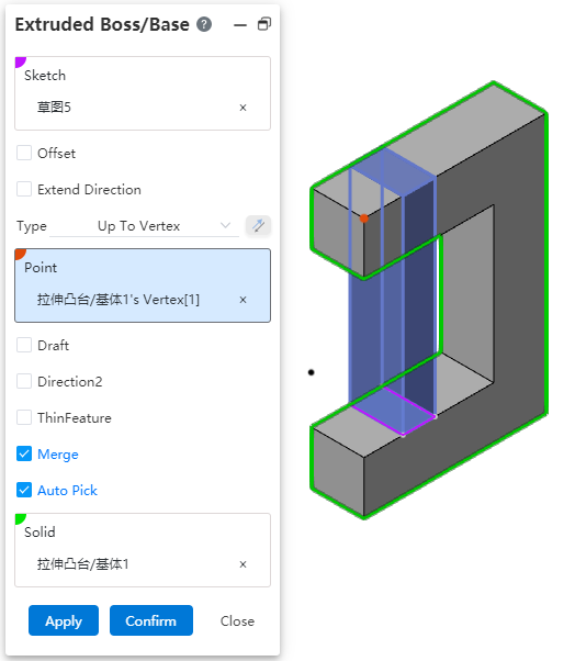
Dialog box control description:
Method:ou can select Shape to Point.
Point:Specify the point to be shaped to. Pick up sketch point, sketch line endpoint, sketch line midpoint, center point, solid vertex, edge line midpoint, origin, coordinate origin, reference point. Lines, curves, arc lines, etc. of sketches and entities that are not closed (have endpoints), and the midpoint or end point nearest to the pickup position is taken when picking up a line.
Other parameters:Consistent with other stretching methods.
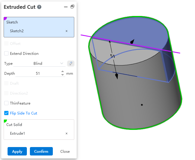
# Reverse side excision
Stretch excision supports reverse lateral excision function. This option can be used when it is not possible to cut the entity through the open loop profile or when it is necessary to preserve the other side of the entity to improve the efficiency of the design.
- Closed contour:The inner part of the contour is cut off by default. When "reverse side cut" is checked, the outer part of the contour is cut off. The scope of action outside the contour is infinite.
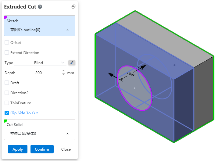
- Open loop contour:When selecting the open loop contour drawn on the solid surface, if the contour divides the selected excision body into two parts, one side can be cut directly without using "thin wall feature", and the other side can be cut if "reverse side excision" is checked.
Note 1:The reverse side excision function cannot be used when selecting an open loop profile that is not drawn on the solid surface.
Note 2:The "reverse side excision" option cannot be used when "Thin-wall Feature" is checked.
# Hole
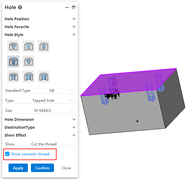
# Cut thread show decorative thread line
When the thread removal option is available, the decorative thread lines can be displayed so that they can be marked by thread lines in the engineering drawing.
# Record the parameters that were last set
Each time you open the hole command, the last parameter used is displayed by default to avoid setting parameters repeatedly.
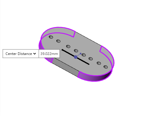
# Notch creation
Hole type Add a notch to create "countersunk hole notch, countersunk hole notch, straight hole notch".
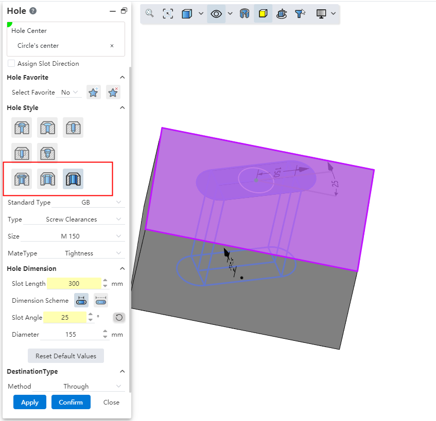
Dialog box control description:
Specify notch direction:The notch direction is aligned with the document absolute coordinate system by default, you can check this to specify other notch directions.
Hole type:You can select the "countersunk hole notch, countersunk hole notch, straight hole notch" type.
Notch length:Set the notch length, which can be selected by the size scheme as shown in the range of the length.
Groove Angle:Make the groove in the default direction based on the rotation of the set Angle, you can click the button behind the reverse rotation.
Other parameters:consistent with the corresponding round hole parameters, such as "countersunk hole notch" and "countersunk hole" parameters.
# Add termination condition types and options
- Given depth:When generating the top cone Angle, you can set whether the depth includes the top cone Angle at the bottom of the hole.

Shape to face:Refer to the stretch cut method, select a face where the hole terminates.
Support plane/surface, optional datum or solid surface of the surface.
Optionally tangent to or across the selected surface.
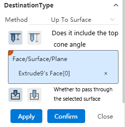
Take tangential as an example:If you choose to include the top cone Angle, then the tip of the hole is tangent to the face; If the top cone Angle is not included, then the shoulder line of the hole is tangent to the face.
To the specified distance from the specified face:Select a face and set the forming distance to this face.
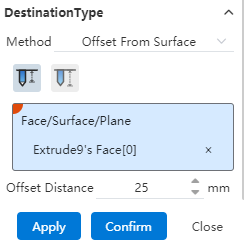
Optionally specify the distance from "shoulder line, top" to this face.
You can enter a range [-0.1, 1e7], where a negative number indicates passing through the selected surface, and an integer indicates not passing through the selected surface to maintain a certain distance from the selected surface.
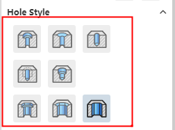
# The icon style shows the hole type
The hole type is now displayed in icon style, making it easy to find the desired type intuitively.
# The hole characteristics show the diameter
The diameter is displayed after the name of the hole feature in the feature panel, making it easy to quickly distinguish holes by diameter.

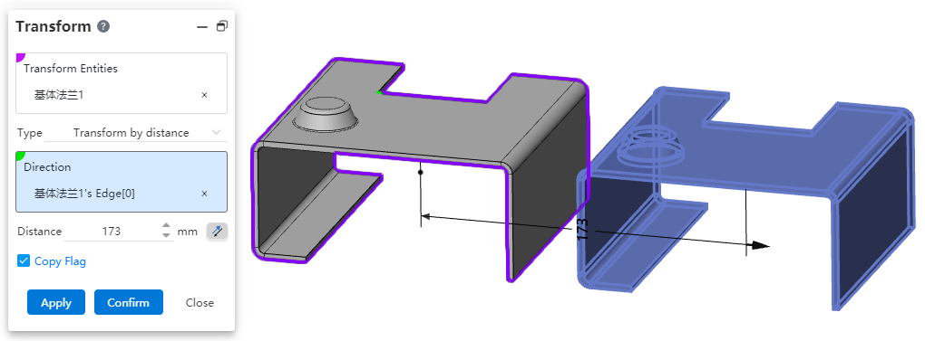
# Transform
# Support for selecting multiple entities
Support to select multiple entities, you can transform all the component entities of the same part at once.
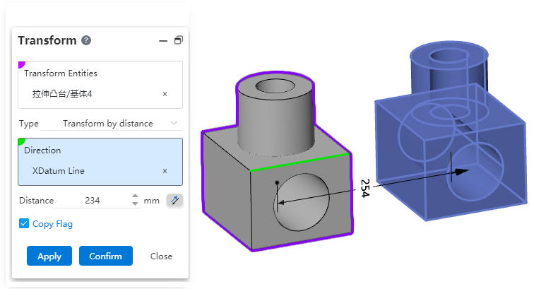
Note:Multiple entities/surfaces are selected, each entity/surface is transformed separately, rather than all entities/surfaces are combined into one whole.
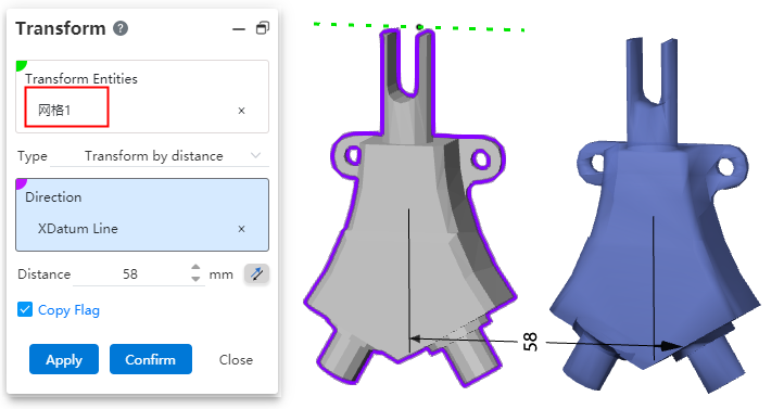
# Support for selection grid
Support for selecting mesh, can handle mesh type geometry.
# Datum Surface
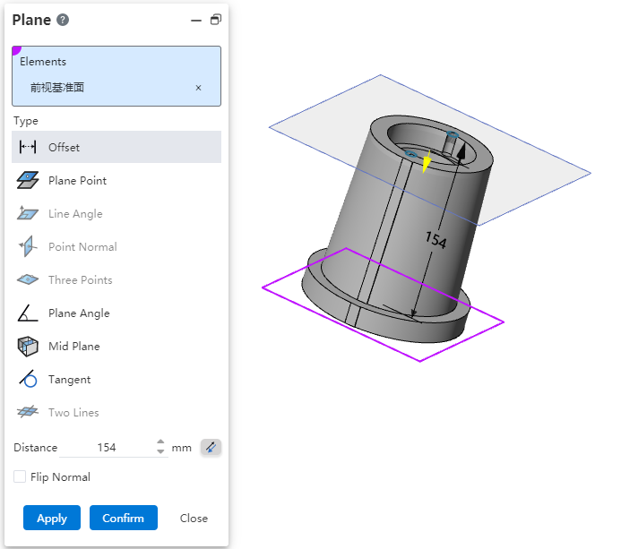
# Quick creation
Added Quick create datum for quick creation of offset datum.
Creation Method 1:
1) In a part or assembly, hold down the Ctrl key while left-clicking any datum in the viewport.
2) The Create datum dialog box pops up, and the datum you clicked is automatically filled.
3) Modify the parameters in the dialog box as needed.
4) Click OK or Apply to finish creating.
Creating Method 2:
1) In a part or assembly, hold down the Ctrl key while left-clicking the mouse over the viewport to drag any datum.
2) The Create datum dialog box pops up, and the datum preview moves with the mouse.
3) Drag to the desired position and release the left mouse button.
4) Modify parameters in the dialog box as needed.
5) Click OK or Apply to finish creating.
Note:In Method 2, you can release the Ctrl key after the datum plane dialog box pops up.
# Datum Line
Base line Adds operation type [points and planes/datum] to quickly create face normals through specified points.
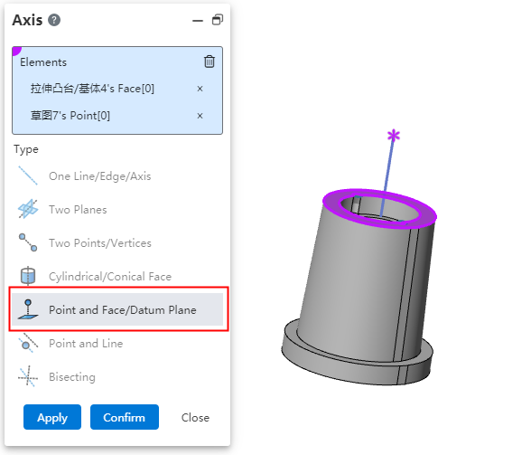
Elements to be picked up:A point and a face.
Point:Sketch point, sketch line endpoint, solid vertex or midpoint, reference point, origin point.
Face:Plane, surface, datum.
Effect:Generate a reference line through the point and perpendicular to the surface.
# Father-son relationship
Paternity can be displayed for selected features, sketches, datums, curves, and surfaces. Used to quickly locate associated features when the parent-child relationship is complex.
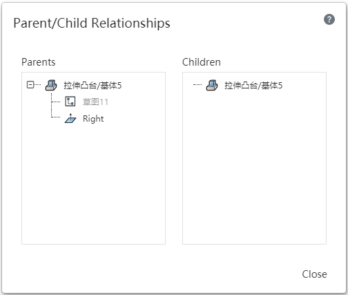
Usage:Select an element in the viewport or feature list and right-click on [parent-child relationship] to display the parent-child relationship table of the feature in the viewport.
Instructions:
Parent feature:Display the features that the option depends on, such as the drawing surface of the sketch, the stretched sketch, etc.
Child feature:Created after the selection and dependent on the selected feature.
Show the sub-features in the order they were created, in the same order as in the feature list.
If the stretch is a subfeature of the sketch, create holes in the stretch body and the holes are the subfeatures of the stretch.
Left click on the item in the list or mouse over the item, and the corresponding element of the viewport is highlighted; Left-click on an item in the list to open the parent-child relationship for that item.
The function of right-clicking an item in a table is the same as the normal right-clicking function.
Note:Right-click in the list of entities, surfaces and curves, and the parent relationship of corresponding features is displayed.
# 3 Curve through the XYZ point in three dimensions
Files imported and exported through XYZ Point's 3D curve feature are common with SOLIDWORKS.
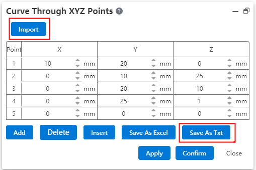
File saved as txt by XYZ point 3D curve function, support using SOLIDWORKS through XYZ point 3D curve function correctly read.
Data files exported by SOLIDWORKS through XYZ point's 3D curve feature can be correctly read by using XYZ point's 3D curve feature.
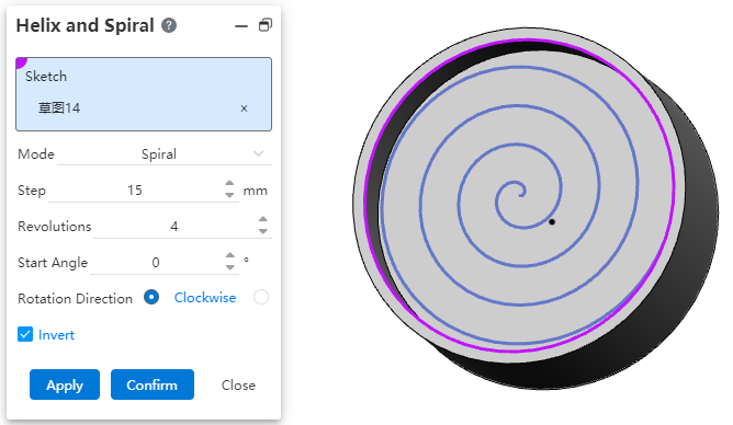
# A Vortex Line
The spiral/Vortex line (formerly Spiral Curve) command supports the creation of vortex lines.
How to use:
1) Click the Helix/Vortex Line command.
2) Select or draw a sketch that contains only one circle.
3) Choose "Vortex Line" for the way you define it.
4) Set parameters such as pitch and starting Angle as needed.
5) Click the Apply or OK button to complete the vortex line.
Dialog box control description:
Sketch:Pick up a sketch that contains only one circle, or pick up the plane to draw a sketch that contains only one circle.
How to define:Select a vortex line to create a vortex line.
Pitch:Set the pitch of the vortex line.
Number of turns:Set the number of turns of the vortex line.
Start Angle:Set the rotation Angle of the start point of the vortex line.
Rotation direction:Set the rotation direction of the vortex line.
Reverse:Check to make the vortex line switch to rotating outside the circle and inside the circle.
# Assemble
# Mate
# Width match
Newly added [width] match type, making it easy to constrain components between two planes.
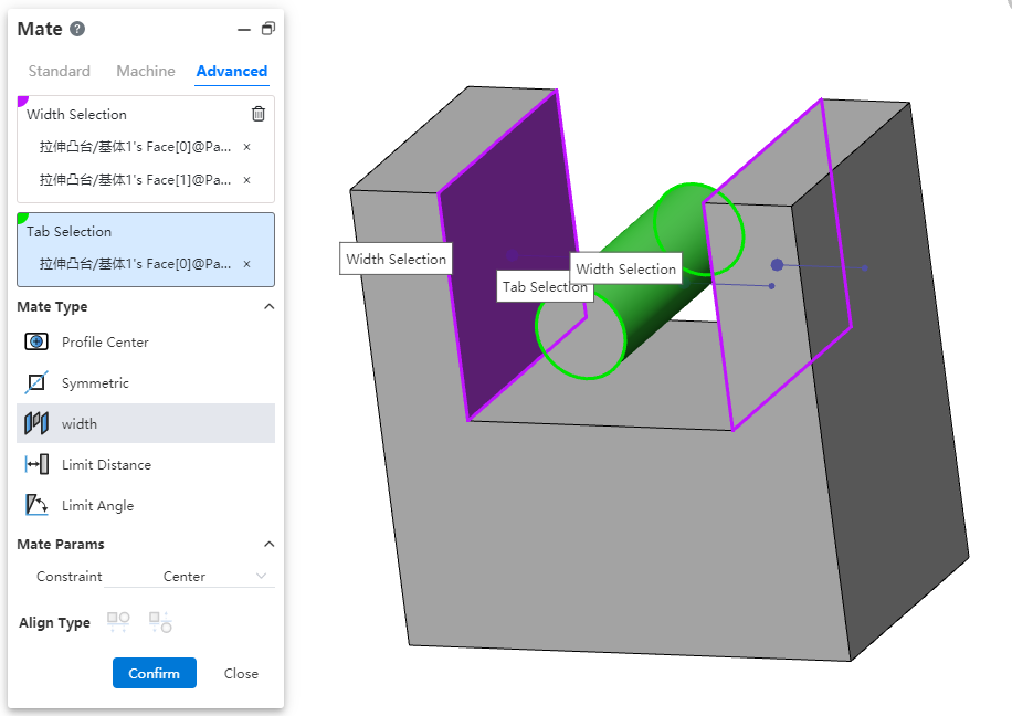
Width reference:Pick up two parallel or non-parallel faces.
Tag reference:Pick two parallel or non-parallel faces, or a cylinder.
Constraint:Select the type of constraint, optionally "Center, free, percentage, size".
Center:The label overlaps with the width reference center.
Free:The position of the label in the width reference is not restricted and can be moved/rotated within the width reference.
Percentage:Limits the position of the label in the width reference by percentage.
Size:Limit the label by size to the location of the width reference.
Different combinations of width references and label references support different types of constraints:
| Combination | Width reference options | Label reference selection | Supported constraints |
| 1 | Two Parallel Faces | Two Parallel Faces | Center, Free, Percentage, Size |
| 2 | Two Parallel Faces | Two Non-Parallel Faces | Center |
| 3 | Two Parallel Faces | Cylindrical Faces | Center, Free, Percentage, Size |
| 4 | Two Non-Parallel Faces | Two Parallel Faces | Center |
| 5 | Two Non-Parallel Faces | Two Non-Parallel Faces | Center, Free, Percentage, Size |
| 6 | Two Non-Parallel Faces | Cylindrical Face | Center |
| 7 | In Combination 1/3/5, the width reference distance (or angle) must be less than or equal to the tag reference distance (or angle, cylindrical diameter). | Center | |
Combination Effect:
Center:Label reference the middle surface of the two planes, the axis of the cylinder and the middle surface of the width reference add the coincidence effect.
Free:The label reference element is located at any position within the width reference range, and the label part moves/rotates within the width reference range, and stops when the move/rotation reaches the position where the element coincides or is tangent (the effect is similar to the restricted distance/Angle).
Percentage:Similar to the constraint of notch scale in mechanical fit.
Size:Combinations 1 and 3 show the distance value, combination 5 shows the Angle value, and the label reference is located at the size specified value.
# Hinge match
New Combination Type: [Hinge] to facilitate constraint of hinges and other parts of doors.

Same-axis center part element:Pick up the part element to which you want to add coaxial.
Overlapping part elements:Pick up the elements of the same part as the coaxial center and add a coincident fit.
The green range below indicates the combination of element types that support picking.
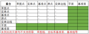
Only elements with the same parts as the axis can be picked up.
Limit Angle:Check this, select the plane belonging to the two parts respectively, set the Angle range of the two faces can be rotated relative to each other in the fit parameters.
The green range below indicates the combination of element types that support picking.
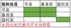
Only elements with the same parts as the axis can be picked up.
Alignment Type:In the same direction or in the opposite direction, the button is available only after both coaxial and coax are selected.
Constraint Effect:when the limit Angle is checked, the part becomes fully constrained, but it still supports rotation within the Angle range; When it is not checked, the effect is equivalent to adding coaxial and coincidence constraints.
# Distance Coordination Optimization
When picking up two elements to coordinate, when the "Distance, Limit Distance" option is selected, the default distance value is displayed as the current distance between the two elements, rather than displaying the default value. This can avoid the problem of relative position offset too much in the distance coordination model.
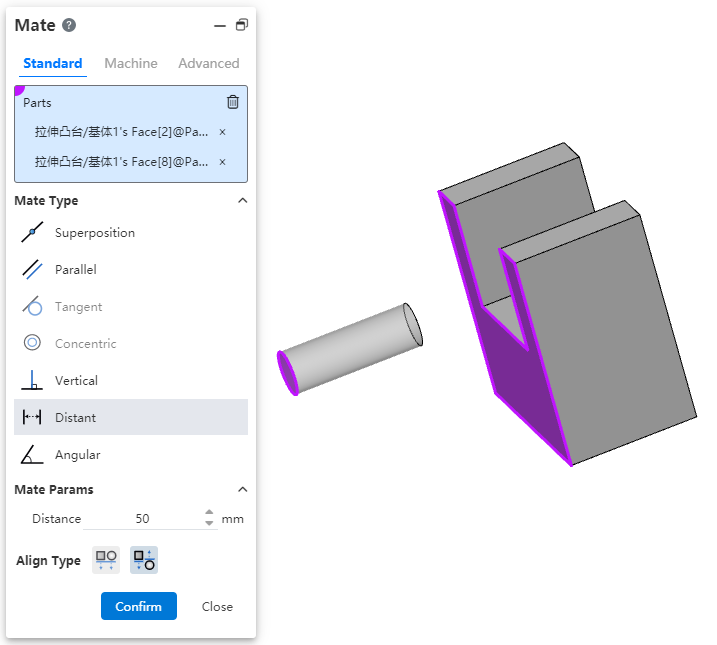
Notice:You must first select the fit element and then change the fit type to "Distance, limit distance" for this function to take effect correctly.
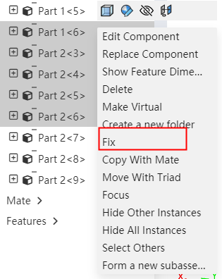
# Multi-select Fixed
Supports picking up multiple components at the same time and adding fixed. Increases the efficiency of fixing a group of components.
# External Reference
In the document, right-click to use the "External Reference" function, list all features, parts, subassemblies, or assemblies in the document, and perform related operations. Intuitively view the documents that contain external references.
- When external references are included in a part or assembly document, right-click (single click) different options in the list to display [External Reference].
Right-click Assembly:Displays all subassemblies, subparts, features, and details in the assembly that contain external references.
Right-click Subassembly:Displays all subassemblies, subparts, features, and details within the subassembly that contain external references.
Right-click Part (Part name in a part or part document):Displays all features and details under the part that contain external references.
Right-click Feature:Displays information about external references to that feature.
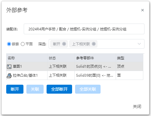
- Dialog box Description:
| Name | Rules |
| Assembly | If the assembly is selected with the right mouse button, its name and path (location within the project and folder) are displayed. If the part is selected with the right mouse button, the external reference information of the part, along with the name and path of the assembly it belongs to, is displayed. |
| Nested/Planar | The style can be selected in the table and the default is nested.
|
| Filter | Filter the displayed content according to the selected status, filtering in real time. |
| Table | Click any item to select the row, and the part or type element in the view will be displayed as selected state, only one row can be selected but cannot select multiple ones. |
| Name, status, entity referred to, type | Show feature or part name, external reference status, referenced part and type. |
| Disassociate | Disassociate the selected external reference. |
| Associate | Associate the selected external reference. |
| All Disassociations | Disassociate all external references. |
| All Associate | Associate all external references. |
| Close | Close the dialog box and save all operations. |
- Refer to the status instructions
| Reference status | Instructions |
|---|---|
| Disassociate | The reference is disconnected and will not automatically update the disconnected reference. You can re-associate it after reconnecting. |
| Up and down association | In the normal state, the external reference is created by default in this status, and the feature remains the latest status, and when the referenced element changes, the feature will also synchronize the update. |
# Disconnect external reference
Disassociate:Changes the selected external reference feature to the disconnected state, after which the existing external reference will not be updated and cannot be restored.
No external reference mode.:After the component is in the editing state during assembly, you can click No External Reference on the command bar to enter (exit) No External reference mode.
In this mode, a feature with an external reference is created and its reference relationship is disconnected.
In this mode, every time you create a feature with an external reference, the message "Currently in no external reference mode, the reference relationship will be broken" is displayed.
You can enter and exit the "No External Reference" mode at any time. The operation does not affect the features that have already been created. For example: when in the "No External Reference" mode, create feature A, and its reference status is disconnected; when exiting the "No External Reference" mode, the reference status of feature A will remain in the disconnected state.
When a feature with external reference is created, the name of the feature and the document name are displayed with special symbols to indicate the reference status.
- Description of symbols and corresponding states
| Instructions | Special symbols |
|---|---|
| A draft, feature, or part that has external reference. | -> |
| A draft, feature, or part that has a disconnected external reference. | ->x |
| A draft, feature, or part that has both connected and disconnected external references. | ->*x |
- If a feature's draft contains external references, the special symbols for the draft will be displayed within square brackets. For example, "->*{->*x}" represents that this feature has both locked and disconnected external references, and its draft contains both external references.
# View reference
In the assembly document, select one or more elements to display a list of fits and edit the fit. It is easy to visually see which fits exist in the element.
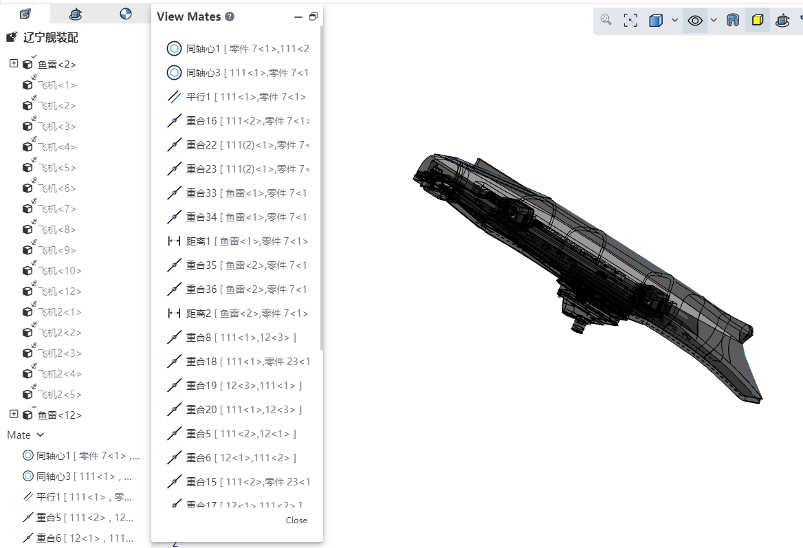
How to use:
1) In the viewport or instance list, select one or more parts, benchmarks, origin and other elements that can participate in the fit.
2) Right-click the [View Reference] function.

3) After clicking, a collaboration list of the selected element is displayed, and the display state of components in the viewport changes.
Parts display status:
When a component has collaboration:All top-level instances in the document are automatically set to transparent mode (the "Transparent" function in the right-click menu of instances). Excluded components are automatically hidden.
Components that were already hidden before opening the collaboration list will become visible but transparent when included, and remain hidden when excluded.
When a component has no mates:All components are automatically set to transparent mode, and there will be no hidden components.
Match list operation:Click an item in the collaboration list with the left mouse button to highlight the corresponding element in the viewport. Right-clicking displays the "Edit" and "Delete" functions, which function similarly to those accessed via a right-click within the collaboration list.
# Replace parts or assemblies
When replacing a part or assembly, you can set a replacement option that allows you to reattach a fit to a new part.
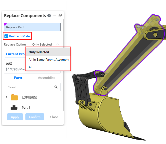
Replacement options:Used to set the replacement range of multi-instance parts, optional "only the selected instance, all of the parent assembly where the instance resides, all."
Only selected instances:Only the selected instances are replaced.
Instances in the parent assembly:The top-level instance of the currently selected instance in the parent assembly. For example, if Part1 is inserted twice in the current assembly and once in a sub-assembly, it will only replace the two instances of Part1 in the current assembly.
All:All instances in the current assembly are replaced, regardless of the level.
Reattach a match:Select this item and click OK. The Reattach a match dialog box is displayed. You can attach a match to the replacement component.
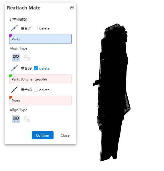
Each mate corresponds to a picking box and a selection for deletion. The picking box is used to select the mate element, while checking the delete option removes that mate.
When no element is picked, the default is that the collaboration element is lost, and the collaboration turns red with an error.
# Parent-child relationship
New parent-child feature in the assembly document for visually viewing the associated elements of a particular element.
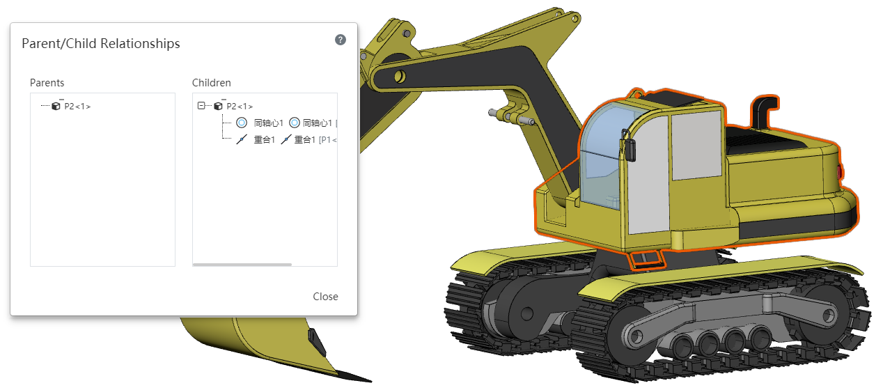
Usage:Select a part, fit or assembly feature in the viewport or feature list and right-click on [Parent relationship] to display the parent-child relationship table of the feature in the viewport.
- Pick up different items to display the parent-child relationship table as follows:
| Items picked up | Parent features | Child Characteristics |
| Selected component (irrespective of hierarchy) | The name of the selected component in the instance list. |
|
| Mate | The two components involved in the mate. | Mate |
| Assembly sketch | 1.Sketch plane or the component to which the sketch plane belongs 2.External elements referenced in the sketch, such as lines in Sketch 2 and lines from Component 3-1 that have added constraints. | Sketches and features created using those sketches. |
| Assembly Stretch Cut | Sketch, direction,cutting volume | Stretch Cut feature |
| Datum | Elements referenced when creating a datum or the components to which those elements belong. | Features and mates created referencing this datum. |
| Array, Mirror | Array components or components that contain the array direction, and sketches. | Features and generated instances. |
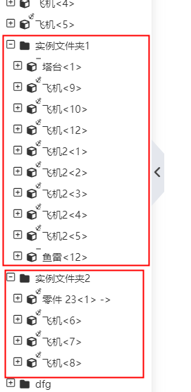
# Grouping instances
In the assembly document, parts, matches, features and other contents can be grouped into folders to achieve group management.
Usage method:
1) After selecting the components, mates, or assembly features that you want to place in the same group in the viewport or feature list, right-click and choose [New Folder].
2) Set the folder name.
3) Click outside the dialog box or press Enter to create the folder.
Note 1:Different content elements cannot be placed in the same folder. For example, you can only select parts, and you cannot mix parts with mates or features.
Note 2:When placing parent and child features that have a specific order into a folder, the order must be maintained, or they will not be able to be placed in the folder.
# Drawing
# Section View
Optimized thread line effect, can be correctly drawn according to GB standard in various scenes.

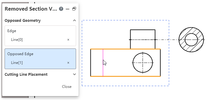
# Removed Section View
New [Removed Section View] command, allowing creation of isometric section views. This view is more concise and intuitive when representing small portions of pipes or similar regions within a large model, as opposed to a full cross-section view.
How to use it:
1) Click on the [Removed Section View] command.
2) Pick up the edges on either side of the section you want to generate in the viewport.
3) Move your mouse between the two edges to see a preview of the cut lines.
4) If the profile preview is as expected, left-click to generate the profile preview; If the cut line preview does not meet expectations, expand the cut line placement option, switch to "Manual", manually specify the cut line endpoint on each of the two sides to generate the profile preview.
5) Move the section preview to the desired position and click the left mouse button to complete the placement.
Associated View:
Support for generating isometric section views from the following types of views: Model View, Perspective View, Section View, Auxiliary View, Exploded Section View.
Support for generating the following views from an isometric section view: Local View, Clipped View.
Note: The perspective direction of the isometric section view is determined by the order in which the edges are selected. After creation, you can select the view and click "Flip Direction" in the dialog box to change the viewpoint.
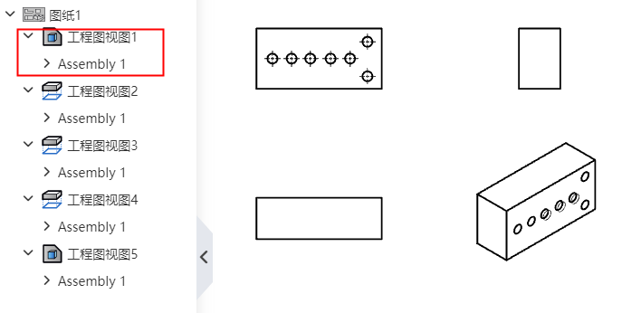
# Model view
# Read 3D view
The Model view supports reading views defined in 3D.
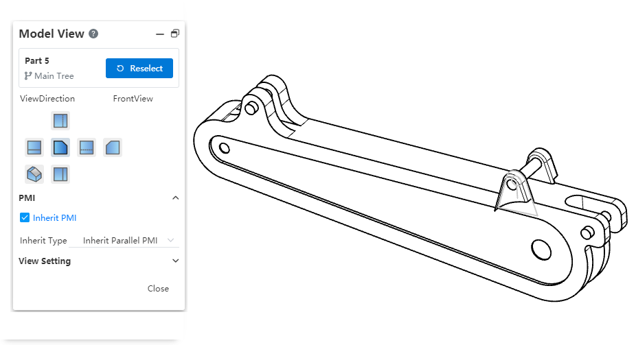
How to use:
1) Press the space bar in the 3D model and click the Named View button to create a custom view.
2) Use the [Model View] command in the project drawing.
3) Select the perspective in the 3D model in the "Custom View" area.
Instructions:
Viewpoints in the "Custom Views" area with a model icon next to their names are viewpoints defined in the 3D model, while those without an icon are viewpoints defined in the drawing.
In the Model View dialog box of the drawing, you cannot delete views that are defined in the 3D model.
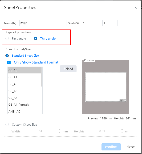
# Switch between first-person and third-person perspectives
Support switching between "First Person Projection" and "Third Person Projection" types to meet the requirements of different standards.
Modify the default viewing Angle mode:
1) Open "System Settings - System Options - Display".
2) Select "First-person Perspective, Third-person Perspective" in the Projection Type.
3) Modifying the default viewpoint does not affect already generated drawings, it only affects subsequent drawings.
Modify the viewpoint method of individual drawings:
1) Right-click on the drawing in the Views panel - Properties.
2) Select "First-person Perspective, Third-person Perspective" in the Projection Type.
3) When switching projection types, previously generated sub-views will reverse to maintain consistency with the new projection type.
# Rotate View
Add a new command called [Rotate View], which rotates the view around its center to a specified angle.
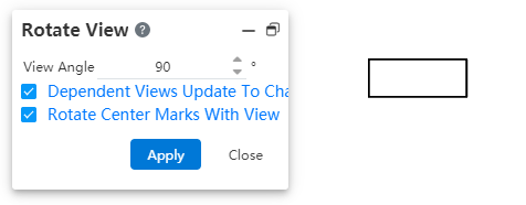
How to use it:
1) Click on the "Rotate View" button in the Lead View toolbar.

2) Click on the view you want to rotate in the viewport.
3) Set the rotation angle through the dialog box or drag and rotate directly in the viewport. The rotation takes effect immediately.
4) Click the "Close" button to end the rotation.
Dialog box control description:
View Angle: Show and set the view rotation angle.
Related views adapt to the new orientation: When checked, the sub-views of the rotated view are regenerated according to the new orientation; if unchecked, the sub-views are still generated in the style where the view is not rotated. Sub-views include existing ones and newly generated ones. Regardless of whether it's checked or not, it does not affect the parent view of the rotated view.
Keep Centerline with View Rotation: When checked, the centerline rotates with the view; when unchecked, the centerline maintains its original direction without change.
Display Rotation Angle: The rotation angle can be displayed in the annotation of "Auxiliary Views, Section Views". This can be configured in System Settings - Document Properties - View Settings, under the option for whether rotation angle should be included in the annotation of each view type. Views that are not rotated do not display a rotation angle.
Note: Detail views cannot be rotated.
# Thread
The decorative thread lines have undergone several optimizations to ensure that the projected or annotated results meet the requirements in specific scenarios.
- When projected as a straight line, support is provided for annotating the outer diameter. As shown by the arrow in the figure, the straight line representing the outer diameter can be annotated with a smart dimension to specify the thread specifications.

- Rear view support for annotation is available. As shown in the figure, the thread lines generated after projecting or cutting in the indicated direction can be annotated with a smart dimension to specify the thread specifications.

- Optimized end limits of effective threads and starting position of thread lines to comply with drawing standards.
# Dimensioning
# Automatic dimensioning
Support for automatic dimensioning. This function can automatically generate most of the dimensions, and then manually adjust and supplement to complete the annotation.
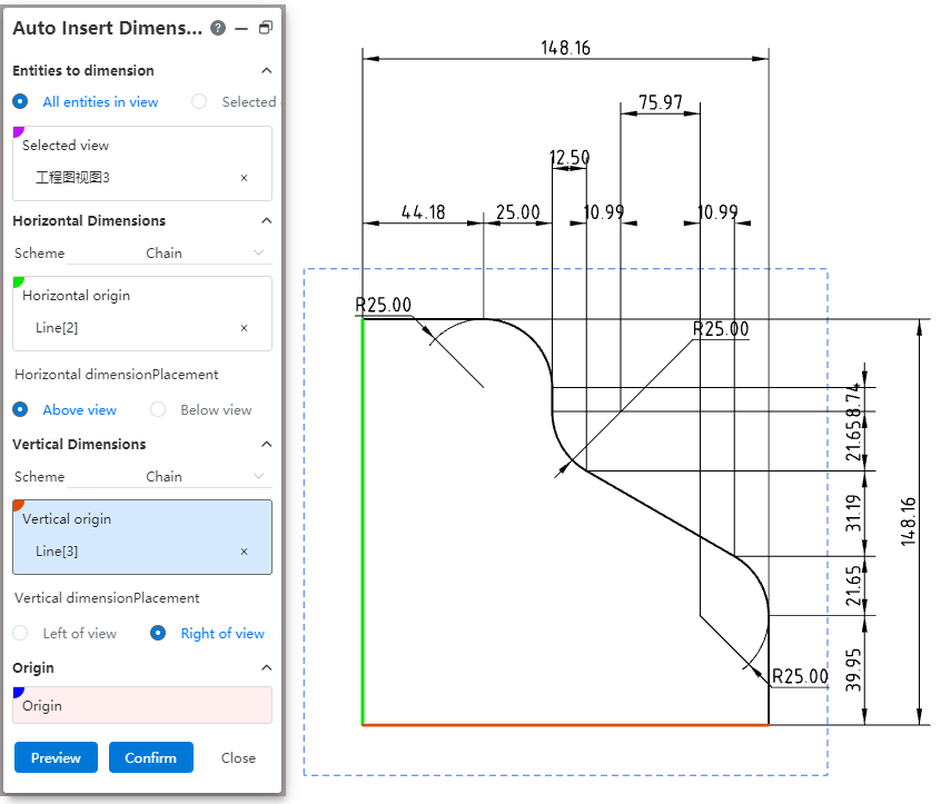
How to use:
1) In the Smart Sizing Command drop-down box, click Automatic Sizing.
2) Select the view you want to annotate in the viewport, and you can specify elements or annotate all elements in the view as needed.
3) Specify the size origin, or the horizontal and numerical size starting points, respectively.
4) Set the size pattern and placement position.
5) Click OK to finish the annotation.
Dialog box control description:
Elements to size: You can select "All elements in View, Specify elements".
Mode: Select the dimensioning mode for horizontal/vertical dimensions respectively, optionally "Chain, reference, dimension chain".
Horizontal/vertical starting point: Select the starting point for the horizontal/vertical size respectively, and can pick up the point, circle or straight line perpendicular to the dimension direction.
Horizontal/Vertical size placement: Select which side of the view to place for the horizontal/vertical dimensions respectively.
Origin: Select this as the starting point for the horizontal/vertical dimensions. Pickable point, circle.
# Max. Min. Size label
The Max/min size can be selected when marking the circle/arc.
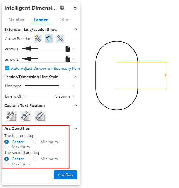
How to use:
1) Click the Smart Size command.
2) Mark the distance between the circle or arc and other elements.
3) The dialog box switches to the "Lead" Tab and modifies the arc condition.
# Dimension boundary optimization
Same asSketch - Dimensional Boundary Optimization.
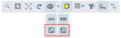
# Virtual Point
Add virtual intersections between elements that belong to the same view/drawing, supporting sketches drawn within the engineering drawing and lines projected in the model.

How to create:
1) Click the Virtual Intersection command in the Draw Points drop-down box.
2) Select two lines that belong to the same view/drawing.
3) Click the OK or Apply button to generate virtual intersections.
See Sketch - Virtual Intersection for other details.
# Record the last setup
Annotations such as size, roughness, form and position tolerances support recording the last setting, and do not need to set the same parameters repeatedly when using the command later.
For example, the shape and position tolerance function, after setting the parameters of the shape and position tolerance, when the command is opened again, the parameters used last time will be automatically filled, which can be used directly or modified on this basis.
# Hole Dimension
- The number of holes generated by the same hole feature can be identified and automatically labeled.

Note: Only the number of holes generated by the same hole feature will be automatically identified. Delete <NUM_INST> in the text box and enter a number to change the number to a custom number.
- Thread depth is not displayed for through-thread.

Note: Only the depth selection of the full penetration mode can be correctly identified.
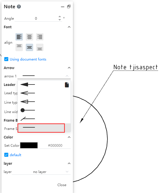
# Notes
- Support for setting rotation angles. Modify the value in the dialog box, comment text in the viewport to rotate.
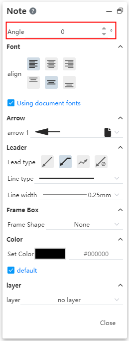
- Add "multi-fold" to the lead type. Select this and click Draw a folded lead in the viewport. Double-click the left button to end the lead.

# Surface Rough
Optimize the surface roughness default orientation. For the surface roughness marked on the dimension boundary line, you can choose which side of the dimension boundary line to mark.
The generated surface roughness provides the option to quickly adjust the direction
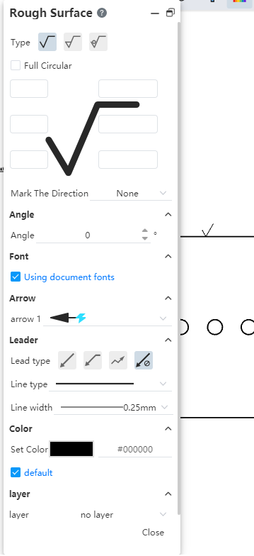
Vertical: The surface roughness faces straight up.
Horizontal: Surface roughness facing horizontally to the left.
Perpendicular: The surface roughness is perpendicular to the element. This is only available when there are no leads and the surface roughness is attached to other elements.
Perpendicular(Reverse): The surface roughness is perpendicular to the element and reversed. This is only available when there are no leads and the surface roughness is attached to other elements.
# Geometric Tolerance
# Merge with dimensioning
Form and position tolerances can be adsorbed on the dimensioning and merged with the dimensioning.

Create form and position tolerances for merge styles:
1) Create dimensioning.
2) To create the form and position tolerance dimensions, place the mouse over the dimension value and click the left mouse button when the dimension annotations are highlighted.
3) Generate the form and position tolerances that merge with the dimensioning.
Merge the form and position tolerances:
1) Create dimensioning.
2) Drag the shape and position tolerance onto the dimensioning and release the mouse when the dimensioning is highlighted.
3) Complete the merge.
To cancel the merge:
1) Select the form and position tolerance for which you want to cancel the merge.
2) Drag the point in the upper left corner of the shape and position tolerance to the empty space.
3) Cancel the merge.
# Add guide lines automatically
The tolerance of form and position is marked on the line. Drag the point control mark at the arrow outward along the line. When the arrow exceeds the line, the guide extension line is automatically added.

# Automatically capture horizontal and vertical
Create or edit the shape and position tolerance mark position to capture when the lead is close to perpendicular to the mark element.

# Auto Balloon
Support to set the sequence number of parts, so that the generation of the desired serial number. Support "according to assembly order, in order, do not change the item number" three options.
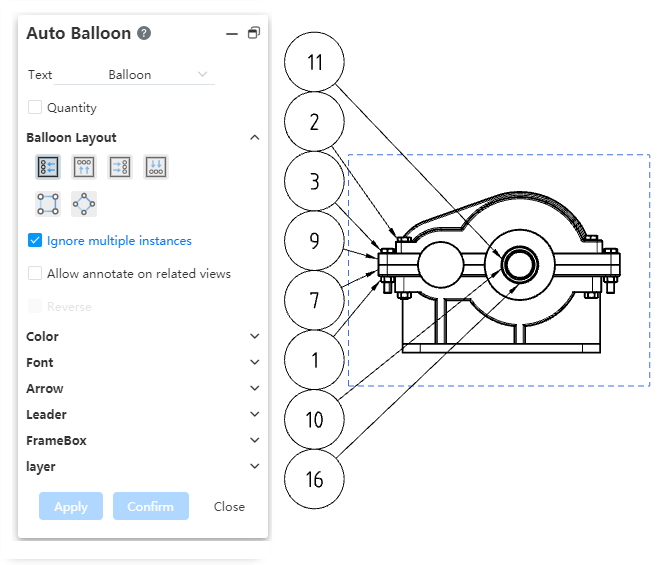
Sort by assembly: Sort by the order of the parts in the assembly. When selecting this item, you can also select "by subassembly order" so that the parts in the subassembly are also arranged in order.
Sort by order: In a fixed direction according to the position of the serial number of the parts in order:
Check the reverse button to sort in reverse order.
By default, the first part is the part whose serial number is in the upper left corner. Click Select the First item to specify a part in the viewport.
The project number can be set as "start from, increment".
Start from:Serial number of the first component. Only a positive integer can be set.
Increment:The increment between the serial numbers of the parts. Only positive integers can be set.
Material detail list can not be used when selecting "Indent - Simple number/Detail number".
Not change balloon: If you select this item, the item number of the current parts is fixed, and the user is forbidden to select "Arrange in order according to the assembly order". And drag to change the order of the rows in the material list, keep the item number unchanged.
Note: The above function can only be used when the material list is present.
# Drag and drop to toggle associated elements
Annotations annotated on elements, you can drag and drop to toggle annotated elements.
This function is effective for part serial number, reference, form and position tolerance, reference target, position label, comment, surface roughness, welding symbol.
For annotations with leads, the element where the lead arrow is located is the associated element. Drag the lead arrow position to switch the associated element. Dragging does not affect the associated element as a whole.
# Comment one to many
A comment command with leads, you can add leads, so that a symbol points to multiple elements.

Add method 1: Select annotation, hold down Ctrl, drag the arrow to create a new lead line.
Add Method 2: Right-click on the lead of the viewport, click Add Branch, create a turning point at the lead click position, use the turning point as the starting point to lead the branch lead and start drawing, drawing in a similar way to drawing a sketch line.
When drawing, click on the blank area to generate a turning point and continue drawing the next section of lead.
When drawing, click on the model face, model edge line, or sketch line to automatically end the drawing.
When drawing, double click on the blank space to manually end the drawing.
When drawing, press Esc key to cancel drawing and clear the lead that has been drawn this time.
Delete method: Right-click the lead of the branch and select "Delete branch" to delete the branch. You cannot delete all branches, keep at least one.
Modify arrow style: Select the control of the right arrow after the annotation and set its style in the pop-up TAB.
Add Turning Point: Right-click on the lead of the viewport and click Add Turning Point to generate a turning point on the lead without adding a branch. When annotated is selected, all the inflection points on the lead (including the inflection points added separately and the inflection points at the branches) are highlighted, and you can drag and drop to modify the lead length and shape. Drag and drop one turning point while the others remain in position.
Commands that support this feature: Comment, surface roughness, welding symbol, part serial number, form and position tolerance.
# Arrow style
Arrow Style Added the "No Arrow" style to create leads without arrows.
# Area hatch and fill
Added [Area Profile/Fill] command to support custom fill model plane area.
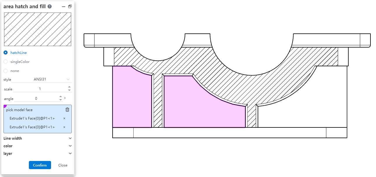
Adding method:
1) Click the [Area Profile/Fill] command.
2) Select the model surface you want to fill in the viewport.
3) Select the pattern to fill in the dialog box.
4) Click OK to finish filling.
How to modify:
1) Select the pattern you want to modify in the viewport.
2) Modify the parameters in the dialog box that pops up.
3) Click OK to finish modifying.
How to delete:
1) Select the pattern you want to delete in the viewport.
2) Press Delete to finish deleting.
Dialog box control description:
Section Line, monochrome, None: Select the type of fill pattern.
Style, Scale, Angle: When selecting the section line type, set the section line specific pattern.
Select model face: Select the face you want to fill.
Line width: Set the pattern line width. If default is selected, the default line width is used.
Color: Set the pattern color, check default to use the default color.
Layer: Set the layer to which the profile line belongs.
Note: Only surfaces that are flat in 3D can be filled.
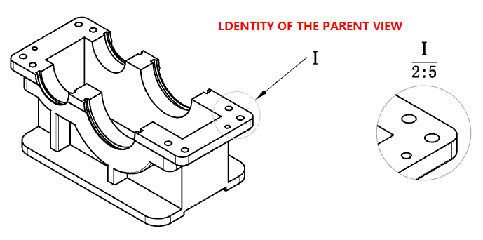
# Detail View
The logo on the local view superview supports drag and drop to adjust the position.
# Material List
Support to modify the order of parts, affect the serial number.

Drag and drop modify order: By dragging up and down the left side of the table representing the row label, you can change the order of parts in the material list.
- Drag and drop is not supported after multiple rows are selected.
- For the "indent" type table, you can only drag and drop parts in the same level to change the order, you can not change the level of the parts. When you drag a parent part, the child part changes the order.
Modify the order through the dialog options:
- Sort by assembly: Check this, do not allow drag and drop to modify the order; And reorder the top parts of the material list according to their order in the assembly, without changing the order of parts in the sub-assembly.
- Sort by subsidiary assembly: This item is available only when "Sort by Assembly" is checked. Check this so that the order of the parts in the subassembly of the Material Specification sheet is reordered in the order in which they are in the assembly.
Related features:
- Starting, increment: The starting number and increment of the parts can be set. Only positive integers can be entered.
- Not change balloon: Check this, drag and drop or dialog box options cause parts to be reordered in the material list, only change the order does not affect the serial number.
# Sketch concealment
Support for one-click concealment of sketches in parts.
Use the "2D Sketch, 3D Sketch" option in the hidden tool in the leading view toolbar to control the hidden state of 2D sketch and 3D sketch in the parts. When the icon is highlighted, the sketch in the display state in the view is displayed; Hide all sketches when the icon is not highlighted. This feature does not affect the hidden state of the part sketches themselves in the drawing view.
Right-click on the sketch of the part in the view/Feature panel, add the option of "Show all sketches/Hide all sketches", and click to show/hide all the sketch of the part in the view. This function affects the implicit state of each sketch of the parts itself in the engineering drawing view.
The hidden state of sketch in engineering drawing only affects the hidden state of sketch of parts in engineering drawing view, and does not affect the hidden state of sketch of parts source document.
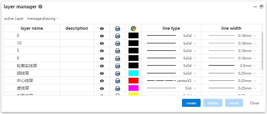
# Layers
Create, manage, and delete layers. Manage the display, color, line and other parameters of views, annotations and other elements in batches through layers.
Layer manipulation:
New layer: Click the Layer Manager command in the comment module. Click the New button, set the layer name and parameters, click in the blank space to finish the new layer.
Delete layer: Click the Layer Manager command in the annotation module. Select the layer you want to delete, click Delete, the confirmation dialog box will pop up to confirm and delete. You are not allowed to delete a layer that is currently in use.
Manage layers: Click the Layer Manager command in the annotation module. Click on the layer parameter you want to modify to make changes.
Activate the layer: Click the Layer Manager command in the annotation module. Select a layer from the Active Layer drop down menu. The selected layer is the default layer for the new element. Optionally, "None, Follow Document properties, Layers 1, 2, 3..." .
- None: The new element belongs to the empty layer.
- Follow Document Properties: The new element belongs to the default layer set in the system Settings for that element - Document Properties. If the element does not have a corresponding system Settings interface, or if the default layer in Document properties is none, then the new element does not belong to any layer.
- Layer 123...: The new element belongs to the layer selected here and the layer name should be displayed.
Modify the layer to which the element belongs: Click the Layer Manager command in the comment module. Select the element you want to modify in the viewport, select the target layer in the dialog box, and click the Move button.
The parameters and effects of the layer
| Parameters | Action | Remarks |
|---|---|---|
| Name | Distinguish layers | Double names are not allowed |
| Instructions | Add the layer's explanatory information as needed | |
| Visible | Controls the hidden state of elements that belong to this layer | |
| Controls whether elements belonging to this layer print | Hidden layers force not to print | |
| Color | Controls the color of elements that belong to this layer | |
| Line type | Controls the lines of the elements that belong to this layer | |
| Line width | Controls the line width of elements that belong to this layer |
:::
- The elements that the layer controls, and what parameters control those elements
| Elements | Control parameters |
|---|---|
| Sketch non-constructed lines | Visible、Print、Color、Line type、Line width |
| Sketch construction lines | Visible、Print、Color |
| Dimensional labeling | Visible、Print、Color |
| Annotation, part serial number, surface roughness, welding symbol, form and position tolerance, reference, reference target, revision cloud, revision symbol, center symbol line, center line and other annotation elements | Visible、Print、Color |
| HatchLine | Visible、Print、Color、Line width |
| HatchLine | Visible、Print、Color |
Note:
| |
- Sketch color: The sketch in the engineering drawing has two color states, "Show the sketch constraint state color, show the color of the layer to which the sketch belongs". Switch through the "Show Constraint State Color" button in the leading view toolbar.

- Project drawing export DWG, DXF: You can choose whether to export hidden layers. Unlayered elements are automatically exported to "Layer 0".
# Single element fade
Support for hiding individual elements in drawings.
How to hide:
1) Right click on the element you want to hide in your viewport.
2) Click "Hide" to finish hiding.
Display mode:
1) Click the "Show Hidden Comments" button in the toolbar of the leading view to enter the "Show Hidden Comments" state.

2) The hidden element appears in light gray, click to make it switch to show state, click again to switch to hidden state.
3) Press Esc to exit the "Show Hidden Comments" state and end the operation.
Elements that support hiding:
Views
Dimension: Contains various sizes such as angles, lengths, chamferes, dimensional chains, hole marks, etc.
Note: Note, part number, group of part number, surface roughness, welding symbol, form and position tolerance, reference, reference target, center symbol line, center line, revision symbol, revision cloud, table (can only be hidden as a whole).
Hidden elements have a driving role and participate in the review:
Example of driver action: If a hidden dimension already exists on the sketch, when you add other dimensions or constraints, the hidden dimension will still participate in the calculation and may result in overconstraints.
Example: After the revision table is hidden, the revision table cannot be added.
# View Association
When you delete a view, keep the subviews of its projection view type.
# Evaluation Tools
# Measurements
# Measuring setup
Add [Settings] option in the measurement dialog box to meet the measurement requirements of different models of products.
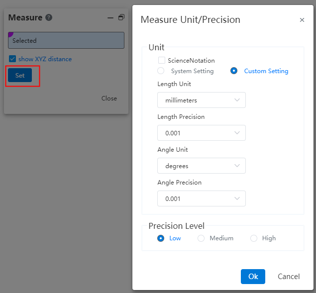
Note:Measurement accuracy refers to the level of precision in the measurement process. The higher the accuracy, the slower the measurement speed.
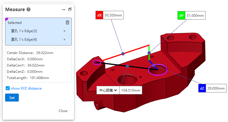
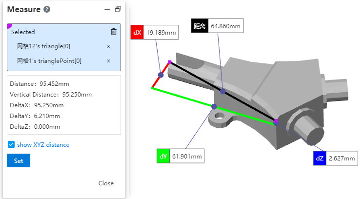
# Show XYZ Distance
In the measurement dialog, check the "Show XYZ Dimensions" option to display the measured values of dX, dY, and dZ between elements in the viewport. This can be used during device installation to inspect dimensions in various directions.
# Quick Measurements
Display the measurement results of the selected element in the bottom right corner of the viewport for real-time viewing of basic information about the selected element.
- Measurement result displayed upon selecting an element
| Selected element | Displayed measurement result |
| Points (Sketch Points, Solid Points, Origin, Reference Points, Center of Mass) | Coordinate values |
| Linear Elements (Sketch Lines, Solid Edges) | Length of a line |
| Circle | Diameter, Center Coordinates of a Circle |
| Curve | Arc Length |
| Cylinder | Diameter |
| Arc or curved surface | Radius |
| Elements other than those mentioned above | No information displayed |
- Measurement results displayed when two elements are selected using Ctrl
| Selected elements | The information displayed |
| Point-to-point, circle, arc, curve, cylindrical surface Line-to-cylindrical surface, line-to-curved surface | Distance、dX、dY、dZ |
| Point--Line | Perpendicular distance |
| Two lines | Non-parallel: Angle Parallel: Perpendicular distance, total length |
| Line--Circle, arc line, curve Circle--Circle, arc line, curve Arc--Arc line, curve Curve-Curve | Distance、dX、dY、dZ、Total length |
| Circle/Arc/Curve--Cylinder surface、Arc surface | Distance、dX、dY、dZ |
| Cylinder surface、Arc surface | Distance、dX、dY、dZ、Total area |
| Two planes | Non-parallel: Angle Parallel: Perpendicular distance |
- Pick 3 or more elements without displaying information
# Measurement Grid
The grid model supports measurement functions for picking, including points, lines, surfaces, and various measurement calculations.
Pick the vertices of a triangular face, display the spatial coordinates of the points, and show the distance between two vertices.
Pick the edges of a triangular face, measure the edge length, and display the angle, distance, and total length between two edges.
Pick a triangular face, measure its area and perimeter. For two partitions of the face, display the angles and total area.
Pick a mesh body, measuring the number of triangular faces and number of vertices. Support picking mesh bodies in both the viewport and feature tree. In the viewport, when the mouse hovers over a triangular face for a short time, three points are displayed. Clicking opens a quick pick dialog that shows a single triangular face and the mesh body containing it.
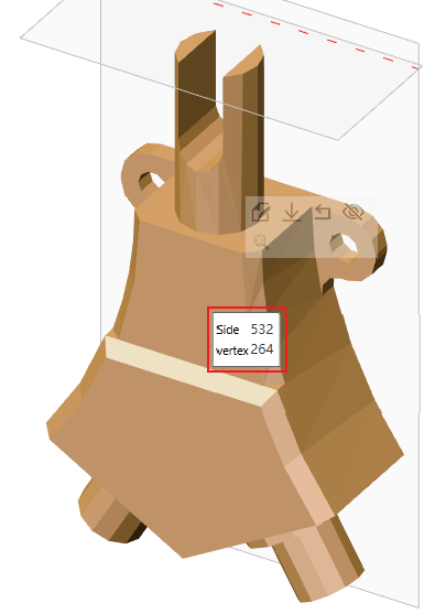
# Display the number of triangular faces and vertices
You can quickly view the number of mesh triangular faces and vertices.
Operation method: Click on the mesh body, hover the mouse over the mesh body for 0.8 seconds, and a pop-up dialog box will appear displaying the number of triangular faces and vertices. It supports picking multiple mesh bodies to display their respective counts.
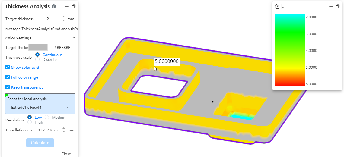
# Thickness Analysis
In the part document, a new command called [Thickness Analysis] is added. It can identify thin and thick areas of the part, determine different thicknesses of the part, and assist designers in evaluating product structure.
How to use:
1) Click on the [Thickness Analysis] command under the Evaluation module.
2) Set the target thickness and other parameters.
3) Select the solid to analyze as required.
4) Click Calculate, and then wait for the calculation to complete before viewing the results.
5) Click Close to finish.
Dialog box element description:
Target thickness:Enter the target thickness value, which will be used as the benchmark for the analysis.
Show thin regions:Display regions in the viewport that are thinner than the target thickness.
Show thick regions:Display regions that are less than and greater than a specific thickness range - these options are mutually exclusive, meaning you must choose one or the other.
Thick region limit:When only "Show Thick Areas" is selected, this option appears, allowing you to input the maximum thickness value to calculate regions that exceed this range.
Treat corners as zero thickness:After checking this box, during the calculation, edges and corners of the part will not be considered thin but treated as having a consistent thickness.
Target thickness color:This color represents the areas that meet the target thickness in the visualization.
Thickness scale:You can choose to display colors either continuously or discretely. In continuous mode, colors transition smoothly between different thickness ranges, while in discrete mode, each thickness range is assigned a distinct color without any gradual transition.
Show color card:When checked, a color palette representing the thickness proportion will appear on the right side of the dialog box. When the thickness ratio is set to discrete, you can specify the number of discrete values in the color palette to define the distinct color intervals for different thickness ranges.
Full color range:The product provides a default gradient range of colors. Unchecking this option allows you to customize the colors according to your preference or specific needs.
Minimum thickness color:This option becomes visible only when the full color range is deselected. It works in conjunction with the target color to control the appearance of the displayed regions.
Keep transparency:This option takes effect when the selected entity has an assigned transparent appearance.
Entity for analysis:This option appears only when there are two or more entities within the part. You must specify the entities for the thickness analysis to be calculated.
Faces for local analysis:This is an optional selection, allowing you to pick multiple faces from the same entity. You can specify certain faces for analysis. If no faces are picked, the default is to calculate the entire entity's thickness. When faces are picked, the calculation will only consider the selected faces.
Resolution:The higher the resolution, the smaller the surface, the more accurate the result, but at the same time the calculation time will be longer. Low: The maximum value of the surrounding box /503. Medium: Maximum value of encircling box /502. High: Max of the encircling box /50.
Tessellation:After picking a mesh, the value will be displayed based on the selected resolution or you can manually input a value. The supported input range is: [0.5, the maximum value of the bounding box / 50 * 3].
Note:When the thickness analysis is activated, curves and surfaces in the part automatically become hidden. When you deactivate the feature, they will revert to their original visibility.
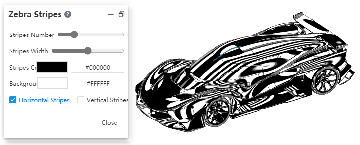
# Zebra Stripes
In the part document, a new command called "Zebra Stripes" has been added. This command is used to identify and inspect surface details, such as continuity of faces, any defects, and evaluate the quality of the surfaces.
How to use:
1) Click on the [Zebra Stripes] command in the Evaluation module.
2) Configure the Zebra Stripes parameters.
3) Display the zebra stripes in real-time in the viewport.
4) Click "Close", and the zebra stripes will remain visible.
5) Click on the "Zebra Stripes" command in the Evaluation module again, and the zebra stripes will disappear, ending the process.
Dialog box element description:
Stripes Number:Display the number of zebra stripes, with more stripes indicating a denser pattern.
Stripes Width:Set the width of the stripes.
Stripes Color:By default, it is white, but you can change it to other colors,Refer to the settings for surface appearance colors.
Background Color:By default, it is black, but it can be changed to other colors.
Horizontal/Vertical Stripes:A binary option: Zebra stripes can be horizontally or vertically aligned.
Surface transition type and corresponding stripe effect:
| Contact | Zebra stripes do not match at the boundaries. |
| Tangency | Zebra stripes match at the boundaries but there are significant direction changes.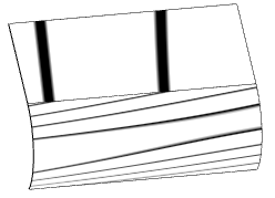 |
| Curvature continuity | Zebra stripes transition smoothly and seamlessly across the boundary. |
# Draft Analysis
Add a new command called [Draft Analysis] in the part documentation. This command is used to visually evaluate whether the model has sufficient draft angle for easy removal from the mold during production.

How to use:
1) Click on the [Draft Analysis] command in the Evaluation module.
2) Set the draft direction and other parameters.
3) The analysis results are displayed in real-time in the viewport.
4) Click OK, and the analysis results will remain visible.
5) Click on the [Draft Analysis] command in the Evaluation module again, and the analysis results disappear, ending the process.
Dialog box element description:
Draft Direction:Select a plane or datum plane as the draft direction.
Draft Angle:Support input range [0, 89], using this angle as the reference draft angle to compare with the angles already present in the model.
Reverse:Click to reverse the direction of the draft analysis.
Adjustment Triad:Check this option to display a 3D axis on the draft direction plane, which can be dragged to adjust the draft direction.
Rotation Angle:Check to show when adjusting with the 3D axis, displaying the current rotation angles around the X/Y/Z axes, which are non-editable.
Face Classification:After checking this option, categorize different faces and assign distinct colors to them. Additionally, count the total number of faces in each category.
Find Steep Faces:This option is only displayed when face classification is selected. When checked, it identifies steep faces based on the draft analysis results. A steep face occurs when some points on the surface meet the draft angle requirement while others do not.
Gradual Transition:This option is only visible when face classification is not selected. When checked, only the faces requiring draft are displayed with a continuous gradient of colors.
Surface faces with draft:This option is only displayed when analyzing surfaces and face classification is enabled. It shows surfaces that meet the draft criteria. If draft is positive on one surface and negative on another, it will not be added to either positive or negative draft categories but will be classified separately under this option.
Positive Draft:Surfaces with an angle relative to the draft direction greater than the reference angle will be displayed in this color, satisfying that condition.
Requires Draft:Surfaces with an angle smaller than the negative reference angle or greater than the positive reference angle will be displayed in this color, fulfilling this condition.
Negative Draft:Surfaces with an angle relative to the draft direction that is less than the negative reference angle will be displayed in this color, satisfying this condition.
Straddle Faces:This is displayed when the face classification is checked, and faces containing positive and negative draws are displayed in this color.
Positive Steep Faces:This is displayed when checking face classification and finding steep faces, and steep faces with positive drawing dies are displayed in this color.
Negative Steep Faces:This is displayed when checking face classification and find steep face, and steep face with negative draw die is displayed in this color.
# Sheet metal
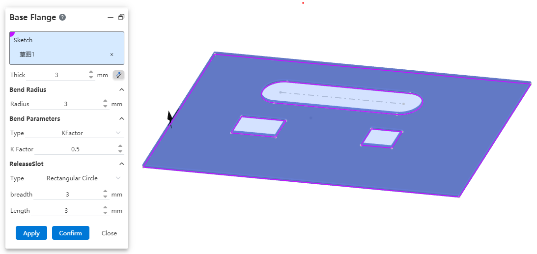
# Base flange
Support the creation of matrix flanges by containing a sketch outline of the nested structure. You can create sheet metal matrix with holes directly from a single sketch, avoiding repeated operations such as stretch cutting after sheet metal creation and improving design efficiency.

# Edge flange
# Automatically add miter joints
Adjacent edges create side flanges and automatically add miters to interference positions. This function can quickly create non-interfering flanges, reduce the time of manual adjustment, and improve design efficiency.
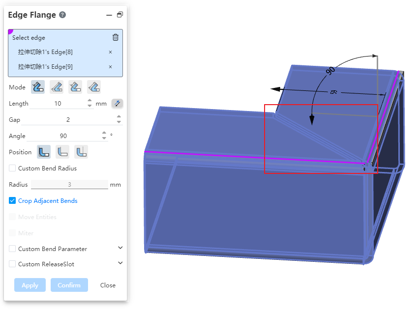
- At the same time, select the edge line that is not connected but equal height and equal bending Angle to add the edge flange, and the miter joint is automatically added to the interference position.
- Set the gap value, you can adjust the size of the gap at the miter.
# Release slot
Tear release slot Added "Notch, extension" option, you can set the specific style of the release slot. You can choose the style that meets the requirements according to the production process or product needs, so that the generated model is more accurate.

- Tear shape styles only work for the outer corners.
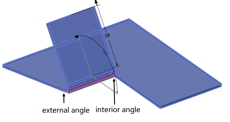
# Miter flange
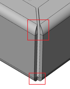
# Corner optimization
The forming effect at the corner of the miter flange is optimized for adjacent edges. The new forming effect can obtain a smaller sheet metal gap and generate a more precise sheet metal model.
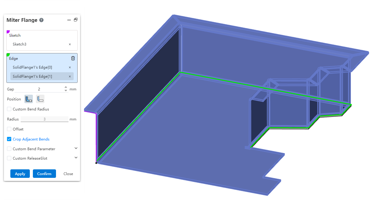
# Continuous edges can be selected
Now the miter flange can be used to select more complex continuous edges, and the software will automatically add miter features in adjacent positions. The efficiency of drawing complex sheet metal by software is improved.
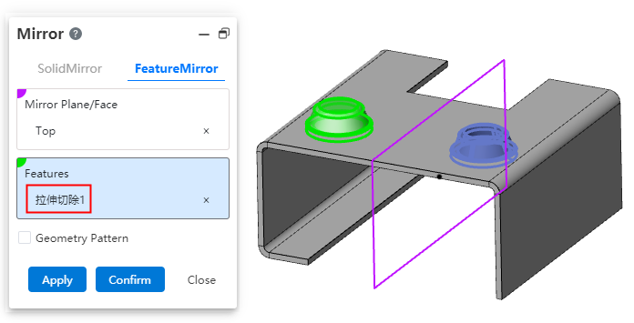
# Entity feature association modeling
Sheet metal stamping, forming features support mirror, array. You can use images and arrays to quickly generate stamping or forming features in batches, improving modeling efficiency.
Sheet metal entities support the modification of position and orientation through the "transform" function, which makes sheet metal modeling more flexible, convenient to adjust the position of sheet metal entities as needed, and improve the efficiency of modifying the model.
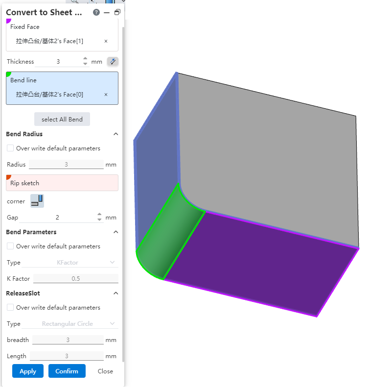
# Convert to sheet metal
Bend the side line to support picking up the arc face. It is convenient to convert the imported sheet metal model into sheet metal, and convert the original bending surface in the model to the bending surface that the system can recognize.
# Forming Tools
If you have some commonly used stamping dies, you can model them and save them to a library. The subsequent use of stamping commands can be directly invoked from the library, quickly generate the same stamping features, improve the efficiency of modeling. Reusing the same stamping die can also reduce your production costs.
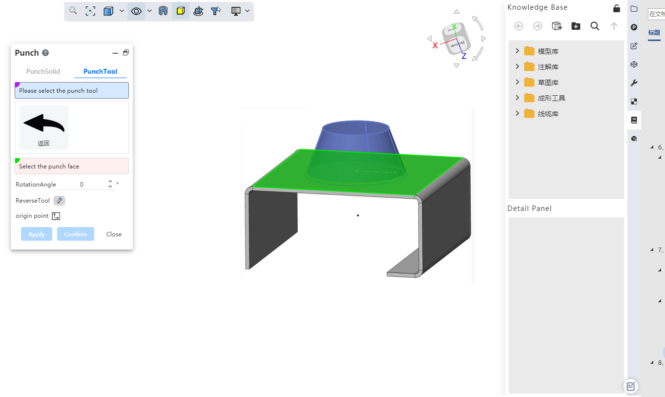
Create a Forming Tool
1) Draw the stamped entity through the entity characterization command.
2) Click on the "Forming Tool" icon to bring up the Forming Tool dialog box.
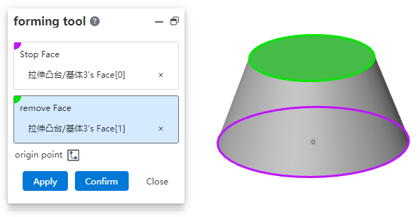
3) Set the stop surface, select the physical surface to be set as the stop surface in the entity.
4) Set the removed surface. In the entity, select the entity surface to be removed. The surface that you do not want to remove is optional.
5) Set the insertion reference point, click the sketch icon to enter the sketch state, and change the insertion point position by dragging or dimensioning.
6) Click OK to complete the creation of the forming tool. At this time, the stamping surface is yellow, the surface to be removed is red, and the other surfaces not involved in stamping are blue.
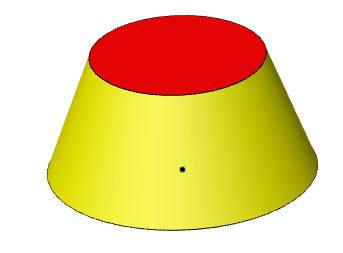
Note:Forming tool features can only be created once in a file.
The forming tool enters the library
1) Open the Knowledge Base panel and click the "Add to Knowledge Base" button.
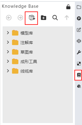
2) File type Select "Forming Tool" and set the file name and location.
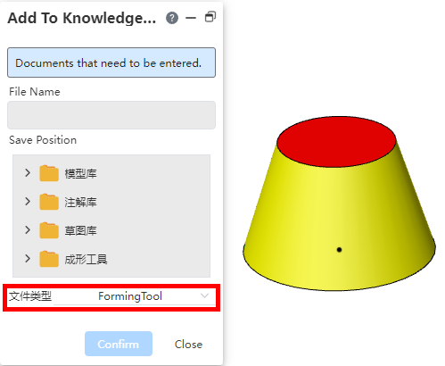
3) Click OK to finish the library.
Note:The Shaping tool feature must be the last feature of the current file for it to be stored correctly.
Forming tool call method one:
1) Sheet metal module toolbar click "stamping" command, switch to the "Stamping tools" Tab page.
2) Select the stamping tool in the Stamping Tool selection box, select the sheet metal plane as the stamping surface in the viewport, and set other options as needed.
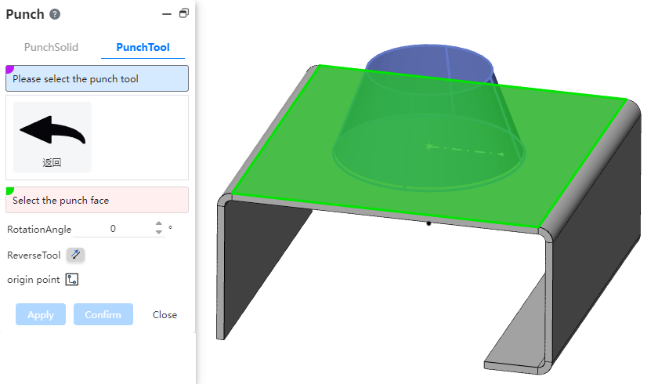
3) Click OK to create the stamping feature.
Forming tool call Method one:
1) Open the stamping tool folder in the knowledge base and select the appropriate stamping tool.
2) Drag the tool selected for stamping directly to the sheet metal surface to be pressed and release the left mouse button.
3) Set additional options as needed in the dialog box that pops up.
4) Click OK to create the punch feature.
Note:The stamping surface must be the plane of the sheet metal.
Manage the forming tool:Right-click the forming tool to be managed in the knowledge base, you can edit, rename, delete operations. Deleting and editing the forming tool does not affect the generated stamping features.
# Data conversion
# Import Creo engineering drawing
Support for importing Creo engineering drawings in .drw format. You can upload the engineering drawings created in Creo along with the associated model. The system will automatically identify the relationship and convert it accordingly.
It is recommended to compress both the engineering drawing and the referenced 3D model files into a single archive before uploading.
# Import CGR, Rhino, and 3DXML files.
Enhance the conversion efficiency for CGR, Rhino, and 3DXML file formats, and optimize color display of such models to improve the software's data conversion performance.
# Import SOLIDWORKS properties
- Support for reading SOLIDWORKS custom property information, which will be displayed in the Custom Attributes section of the BOM module and can be correctly read by the engineering drawing bill of materials.
The property names in the Summary tab will be named as "Summary-Property Name" to avoid naming conflicts with regular properties, while other property names will remain unchanged.
All properties are read as fixed attribute values, such as mass, which will be read as its specific numerical value at the time of upload.
# Import points
When importing a model, you can choose whether to import spatial points. You can use this feature to import spatial points generated in other software and use them as a reference for modeling.
- Check the "Read Points" option under "System Settings - Import - General" to enable importing spatial points.
# Import Setting
The import settings are more comprehensive, allowing for greater control over the import results.
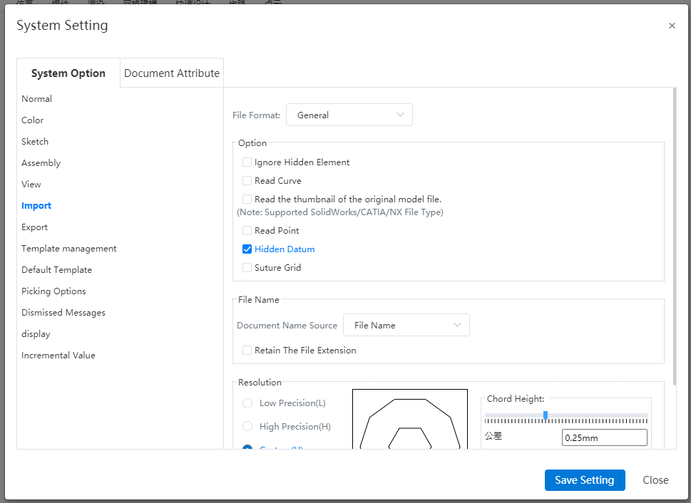
New feature visibility settings for reference planes. This allows you to control whether the imported model's reference planes should be displayed by default or hidden by default.
New feature: Mesh import mode settings. You can choose whether to sew the mesh, where if sewn it will be imported as a single entity with only one mesh in the Features panel; if not sewn, the mesh will be imported in separate segments, with each segment appearing as a separate mesh in the Features panel.
# Collaboration
# Template
Supports sharing document templates and custom property templates. You can share templates that you have created with others, allowing your partners to quickly use specified templates to create documents that meet the required specifications. In addition, when you share a document, you can also choose to synchronize and share the template used by the document.
The following example explains sharing a document template. The procedure for sharing a custom property template is the same.
Method One for Sharing:
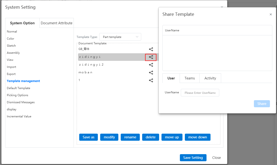
1) Open System Settings - Template Management - Part/Assembly/Drawing Template.
2) Click the Share button following the template you want to share.
3) Set the target user/team/campaign.
4) Click the Share button to complete the sharing process.
Method Two for Sharing:
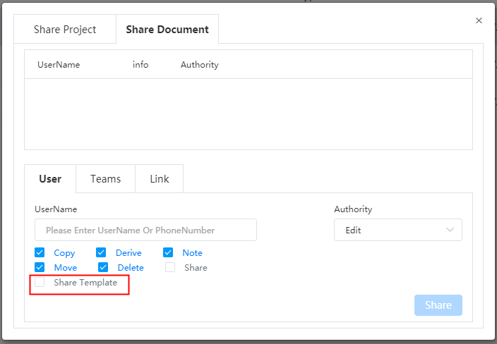
1) When sharing a project or document, check the box "Share template".
2) Click Share, and the templates referenced in the project or document are synced and shared.
Use templates:
1) Click "New Document".
2) In the template dropdown menu, select the shared template which will have a symbol indicator.
3) Click "OK" or "Create" to finish setting up the document using the selected template.
Note:The template cannot be cancelled after it has been shared. After sharing, the shared template is not associated with the source template.
# Document Sharing
Supports sharing individual documents. You have the option to share a single document within a project, rather than having to share the entire project. For shared projects, you can individually modify access permissions for specific documents. This feature greatly enhances permission control flexibility, allowing you to precisely manage access rights on a per-document basis.
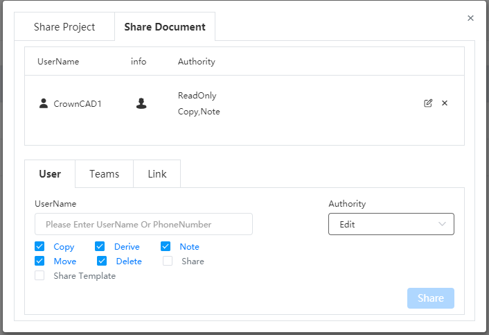
How to share:
1) Click the  button after the document name within the project, or click the button on the title bar after opening the document.
2) Switch to the "Share Document" tab.
3) Set the target user(s)/team(s)/activity and permissions.
4) Click "Share" to complete the sharing process.
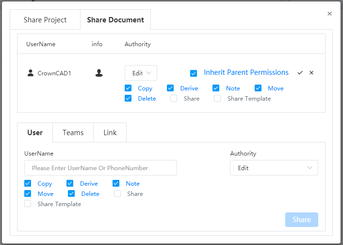
When a project with a document is shared along with the document, the permissions set on the document have higher priority than those set at the project level. This means that the specific access rights granted to the document supersede any general permissions assigned to the project in which it is housed.
Check the "Inherit Parent Permissions" option to make the document's permissions identical to those of the project it resides in.
# Team
# Team Management
Optimize the team list, allowing you to quickly locate the desired team through either chronological order by creation time or a search function.
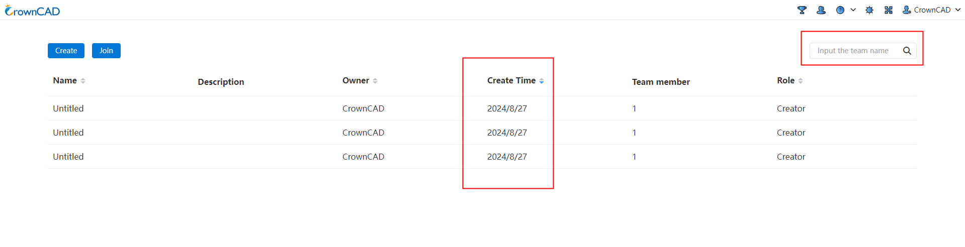
- Add a "Creation Time" column to the team list, which displays when each team was created. The default sorting order for the list should be in reverse chronological order, with the most recently created teams appearing first.
- Add a sorting function to the title bar, supporting sorting by name, owner, creation time, and user role.
- Add team search functionality, allowing users to search for teams by name.
# Create Team
Enhance the team management page interface, incorporating features like invitation links. This results in a cleaner and more visually appealing layout, while also providing more versatile methods for inviting members, thereby making it more convenient for you to utilize the team functionalities.
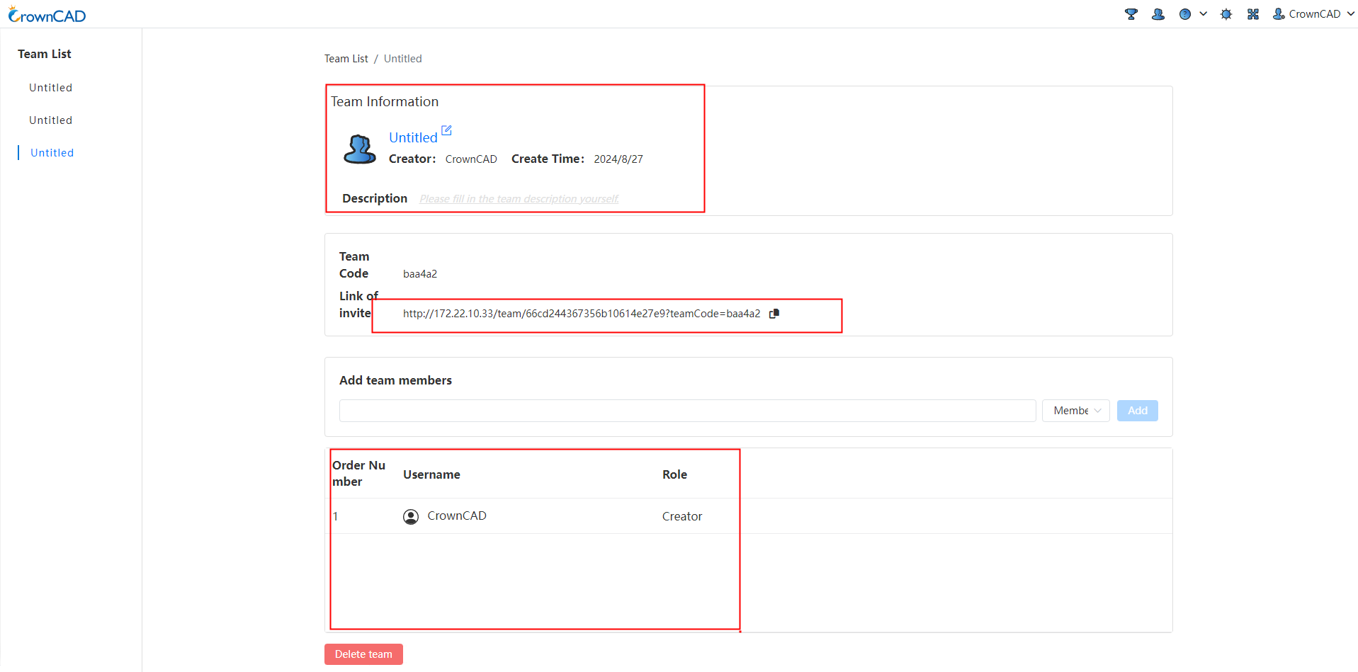
Add invitation links, which allow non-team members to join without needing to enter a team code, streamlining the process of quickly adding new members.
Improve the display of the member list by adding a title bar and a sequence number column.
# Project Manage
Optimize control for different roles over projects, streamline the project management workflow within teams.

Add a project search feature that enables users to quickly locate the desired project or folder.
Add a "Share" button (right-click option) for team creators and project/folder managers, enabling them to share team projects with others.
Add a "Cancel" button (right-click option) for team creators on projects, allowing them to revoke projects that other members have shared with the team, thus facilitating better team project management.
When a shared project is selected with "Copy" permissions, all users are allowed to copy the team project to their personal account, and the project owner will be changed to the individual user.
Add a "Team Copy" button (right-click option) for team creators and project managers, allowing them to copy projects within the team.
Team member permissions:
| Role | Authority |
| Team creator | For projects/folders created within the team, support for project opening, opening in a new tab, project permissions, renaming, copying, team copy, sharing, details, moving, and placing in trash are allowed. For projects shared with the team, support for project opening, opening in a new tab, copying, team copy, sharing, canceling, details, and moving are allowed. The "Copy" and "Team Copy" buttons for the creator will be controlled by the sharing copy permission. For shared projects, the right-click menu will only show these buttons if the "Copy" permission is enabled. |
| Admin | For projects/folders created within the team, support for project opening, opening in a new tab, renaming, copying, team copy, sharing, details, moving, and placing in trash are allowed. For projects shared with the team, support for project opening, opening in a new tab, copying, team copy, sharing, details, and moving are allowed. Note that the "Cancel" and "Copy" buttons for the creator will be controlled by the sharing copy permission; if the "Copy" permission is not enabled, these buttons will not appear in the right-click menu for shared projects. Management's right-click "Copy" and "Team Copy" buttons are controlled by the sharing copy permission. For shared projects, the right-click menu will only display these buttons if the "Copy" permission is selected. |
| Member | For projects/folders created within the team, support for project opening, opening in a new tab, copying, and accessing details are allowed. Renaming, team copy, sharing, moving, and placing in trash permissions may be restricted or granted based on additional settings or roles within the team. For projects shared with the team, support for project opening, opening in a new tab, copying, and accessing details are allowed. Similar to those created within the team, other actions like renaming, team copy, sharing, moving, and placing in trash might have different permission levels depending on the team's configurations and user roles. Member's right-click "Copy" button is controlled by the sharing copy permission. For shared projects, the right-click menu will only show the "Copy" button if the copy permission has been granted in the sharing settings. |
Right click menu:
| Menu options | Instructions |
| Project Permission | Support permission control for team created projects, allowing team created projects to copy and archive mode.
|
| Copy | Copy the team project into the individual project.
|
| Copy within the team | Support for project/folder replication within a team, after the copy is generated in the team, and the owner is changed to the team name.
|
| Move | Move items within a team, not allowed to move into individual items. And change the move to dialog box "My Project" in the team to "Team Project". |
| Cancel | Support cancelling items shared by other members to the team for easier team project management.
|
| Share | Support sharing team projects to users, teams, and events.
|
# System Settings
# Document attribute
# Drawing standards
A number of new options have been added to the drawing standard to give you more control over the content of your drawing.
# Trailing zeros
In the "System Settings - Document Properties - Drawing Criteria - Size" screen, set the display effect of the lead zero and trailing zero values of the number.

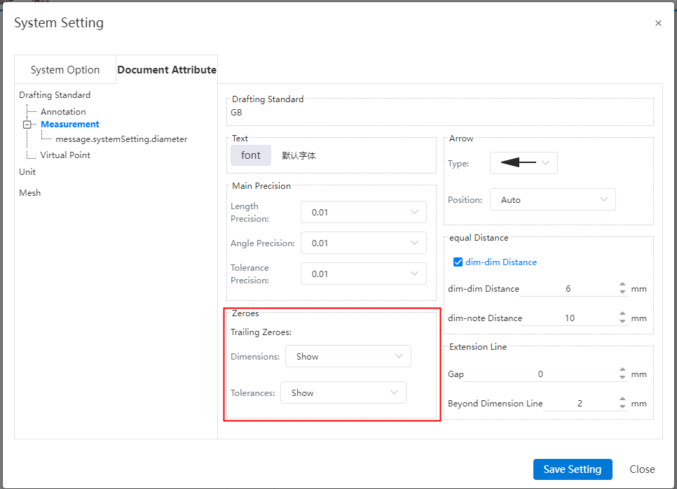
Zero display mode option description:
Display:Display zero value
Remove:Hide the zero value
Remove only if value is zero:Remove trailing zeros when value is 0, keep trailing zeros for non-0 numbers.
# Dimensional boundary line
In "System Settings - Document Properties - Size", you can set the size boundary parameters to affect the default generation effect of the size boundary.
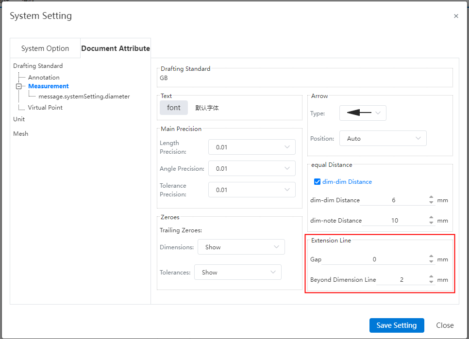
Gap:The gap between the size boundary line and the annotation element.
Beyond the size line length:The length of the size boundary line beyond the size line.
# Units
# Rounding decimals
Rounding decimals can be set in "System Settings - Document Properties - Units", you can set the desired decimal rounding rules according to your needs.
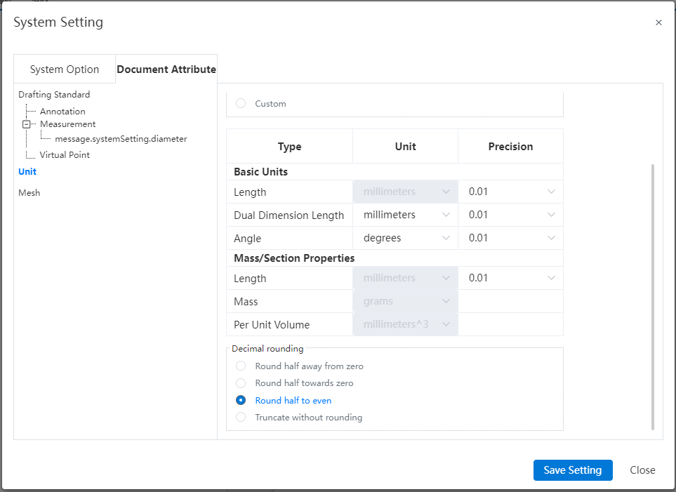
| Way | Instructions |
|---|---|
| Round up and round up | The rounding method of rounding the number 5. Example: one decimal place from 46.15 becomes 46.2. |
| Take the whole add zero | Round up five to six. For example: the decimal place of 46.15 becomes 46.1. |
| Take the integer match | Number 5 Remove the integer method of the number of digits. When the first digit is even, the digit remains the same. For example: the decimal place of 46.25 becomes 46.2. When the first digit is odd, that digit is rounded up to the next even digit. This method is also known as the numerical reduction rule. For example, the decimal place of 46.15 becomes 46.2. |
| Truncate without rounding | Method of deleting bits without rounding. Example: The decimal place of 46.19 becomes 46.1. |
- Rounding only affects the displayed value and does not change the actual value.
# Units
In "System Settings - Document Properties - Units" you can set units for size and quality, providing rich setting options.
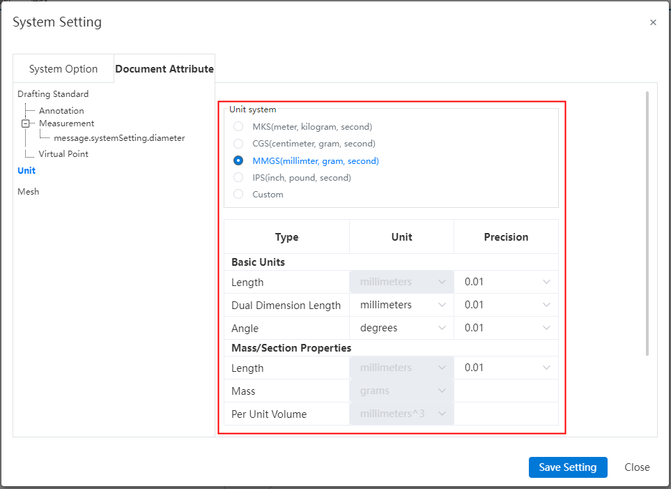
The unit system is the combination of units preset by the system. You can select the preset unit system or set it to any combination of various types of values after customization.
# Custom
# Keyboard
The shortcut key supports the combination of letters and numbers. For example, the stretching boss command can be set to L+1. Meet your operating habits.
For commands that have an icon, display the icon before the command to make it more intuitive. Make it easy to quickly find the commands you want.
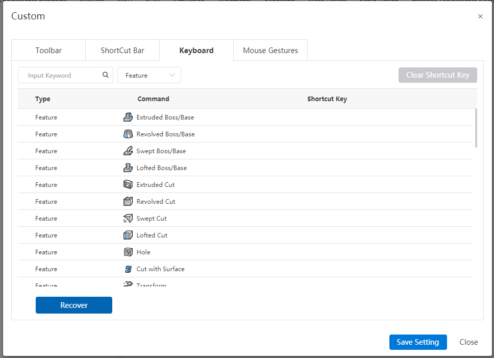
Shortcuts in sketches are common in part sketches, assembly sketches, and engineering sketches, and can be applied in all document sketches after setting the shortcut keys. It is easy for you to use the same set of operation shortcuts in different modules, avoiding repeated Settings.
The Draw Sketch command opens automatically when the sketch command is enabled outside of the sketch (except for engineering drawings) and has been opened after entering the sketch. You can directly use the sketch command shortcut key to smoothly enter the sketch and start drawing the sketch, improving the drawing efficiency.
# Applications
# Set the size increment value
You can customize the value you add or subtract when you click the value entry box arrow to match the size of the model you are modeling.

How to modify:
1) Viewport edit size (sketch size, feature size, etc.).
2) Click Reset Increment value and enter the increment value you want to set.
3) Enter and enter or click on an existing value to complete the setting.
4) Click the Add or subtract arrow in the Size Values dialog box to add or subtract with the set value.
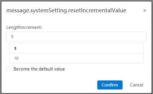
Become the default:Click on a value after checking it to modify the default value set in system Settings, which takes effect for all sizes.
System Settings:Modify the default increment value in System Settings - System Options - Increment Value.
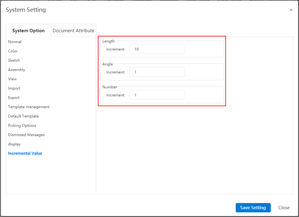
# Toolbars
- Add toolbar options in Custom - Toolbar and set the toolbar available under that module by module. More intuitive control of the toolbars available in different modules.
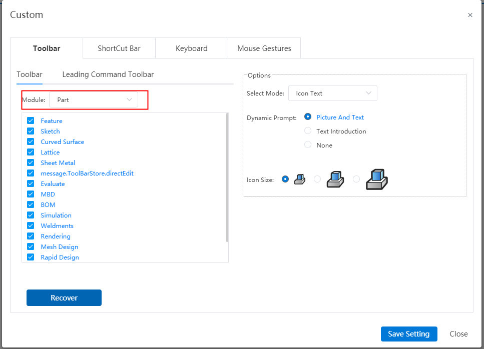
You can disable the toolbar by right-clicking a blank position or a tool name.
The leading command bar supports hiding. Right-click a blank position in the toolbar and cancel "Leading Toolbar - View" to hide it completely. You can set whether the toolbar is displayed in the viewport according to your needs, and you can specifically set the display and hiding of individual commands in this toolbar.
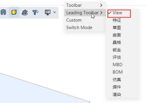
# Open the drawing
The Open drawing feature is more diverse in the scenarios available, and you can quickly open the associated drawings for this document in most modeling scenarios.
In the assembly document, select a part in the instance list and right-click to add the function of "Open Engineering Drawing".
- This function is not displayed when multiple selections are made.
- External documents When you open a project drawing, you can jump to the project drawing when the document is associated with the project drawing. If there is no associated project drawing, you can manually select the project drawing.
In the assembly or part document, right-click in the blank area of the viewport to add the function of "Open Engineering drawing" to open the engineering drawing of the current document.
# Account management
# Account cancellation
Support for logging out of your account in your personal Settings.
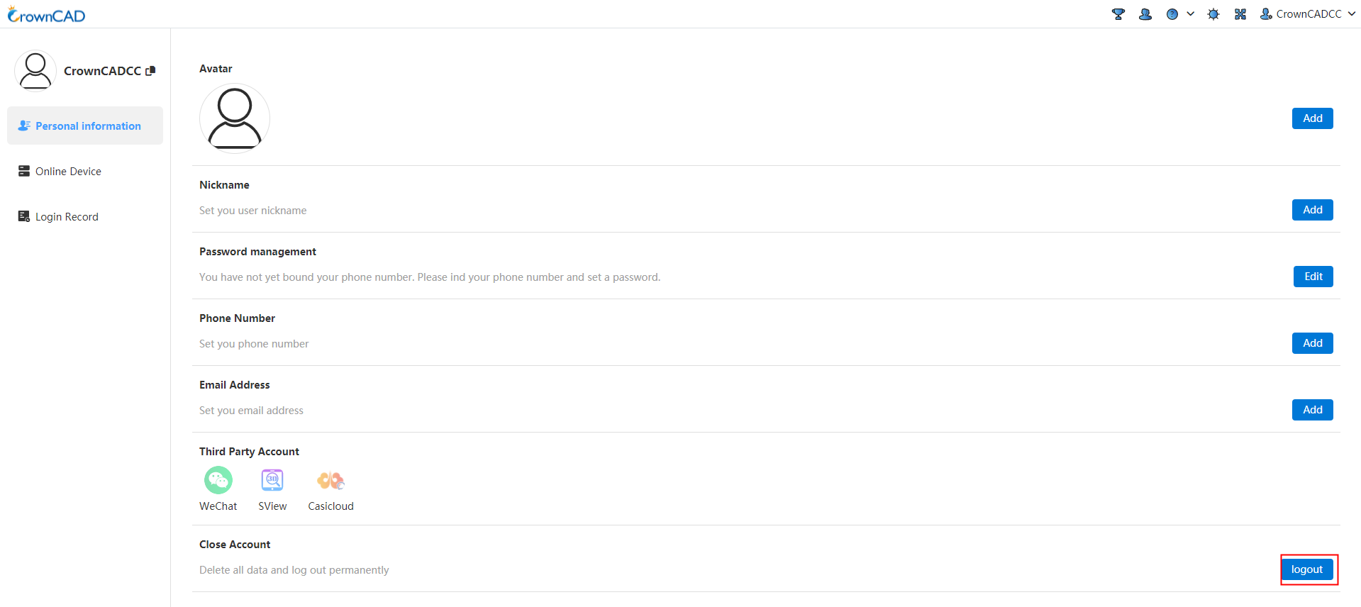
How to log out:
1)Click your profile picture in the top right corner and select Personal Settings - Personal Information.
2)Click Log Off.
3)Complete the verification as required.
4)Complete logout.
Note:A cancelled account can be re-registered as a new account.
# Change your phone number
You can change a bound mobile phone number.
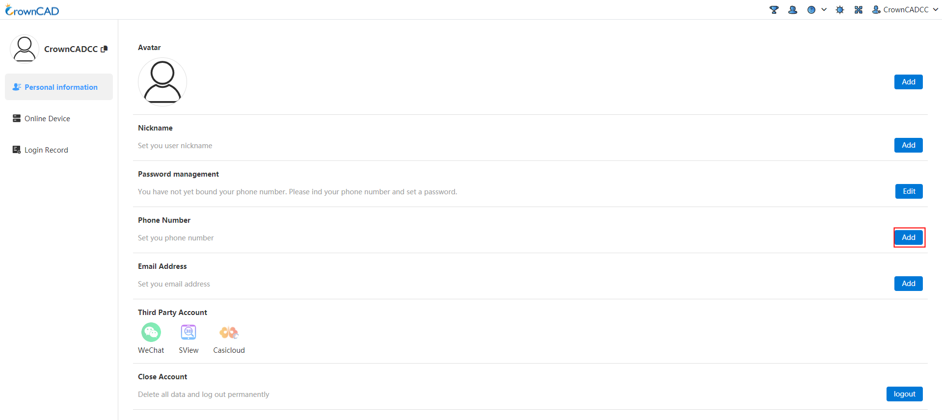
Editing method:
1) Click your profile picture in the top right corner and select Personal Settings - Personal Information.
2) Click Mobile Number - Edit.
3) Complete the verification as required.
4) Finish editing.
# Adaptive
Added double click Middle key adaptive function. Just double click the middle key on the element, and the viewport can quickly adapt to zoom and improve operation efficiency.
How to use:
1) In a part or assembly document, the mouse is placed over the element in the viewport.
2) Double click the middle mouse button after the element is highlighted, and the viewport ADAPTS itself.
# Render
# Grid settings appearance
Supports setting the color of positive and negative faces for grid bodies to view the specific structure of the grid model intuitively.
Open the settings appearance, and in the Entities/Surface tab page, support picking up grid bodies and setting their appearance.
You can pick up one or more grid bodies in the viewport or list, set parameters and rules with the same appearance as the entity.
The color is only applied to the front faces of the grid body, and the color of the back face is as described in the precondition.
The priority of the grid body appearance is equal to that of the entity.
In the "System Settings - Document Properties - Grid" menu, you can select the grid rendering mode.
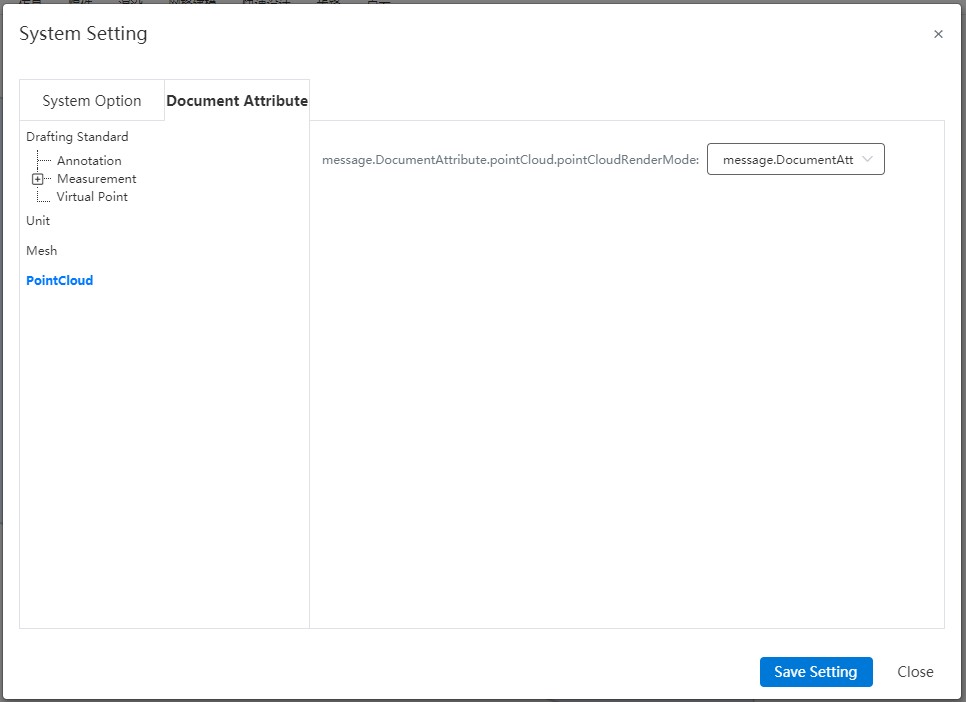
The default is to render one face, and the colors on the face in the viewport are displayed only, which can be modified through setting appearance.
When selecting double-sided rendering, the color of both front and back faces will be displayed, and the back color can be set.
# Grid pick
For the special geometric body composed of large triangular faces, perform optimization of picking in different scenarios.
In the viewport, support grid body highlighting and box selection, which do not support single triangle face picking; in the [Measure] and [Grid to Surface] commands, single triangle face picking is supported for measuring detailed parameters of the grid.
Click on the grid body, the mouse remains at the grid body for 0.8 seconds, a pop-up information box is displayed, showing the number of triangular faces and vertexes, and multiple grid bodies can be displayed by picking up.

# Perspective camera
Supports viewing the model using a perspective view. When this function is turned on, you can observe the model in a similar perspective view as in real life. Combined with real rendering functions, you can get a very impressive display effect.
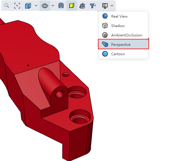
# Libraries/Templates
# Library of standard parts
Add national standard bearings. You can directly call our preset bearing model to improve design efficiency.
# Batch tool
# Batch Name change
Batch change the name of the created file. When you have a large number of parts that need to be named according to a certain rule, using this function can free you from tedious repetitive work and greatly improve work efficiency.
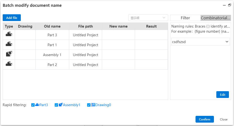
This function can be called in the parts, assembly, engineering drawing interface.
Click the "Batch name change" icon to enter the batch name change dialog box. When the current document is an assembly, the document list will display all the parts contained in the current assembly (no matter which project the parts are located in); When the current document is a part, the document list only shows the current part.
Filter quickly, filtering the files in the list by checking the corresponding file type.
Level filtering, select the level type and filter the list of documents by level.
Attribute filtering, enter the attribute name and attribute value, and filter the document list by attribute.
Click "Add File" option to add other parts.
Click "Display Items" to display items in the document list to make explicit Settings.
Switch the saving mode by clicking the checkbox.
Name Modification Method 1:Click the new name in the form and fill in the new name after the change.
Name Modification Method 2:Select the combination name and automatically generate it according to the set naming method. In this way, the name can be combined from custom attributes.
Click Modify name, after the name is successfully modified, the result column will show success, and the unsuccessful column will show failure.
Click Close to close the current window.
# Batch Modify properties
Batch edit the created model properties, such as modifying, adding, deleting, etc. When you have a large number of parts need to set properties according to certain rules, using this function can free you from tedious repetitive labor, and greatly improve work efficiency.
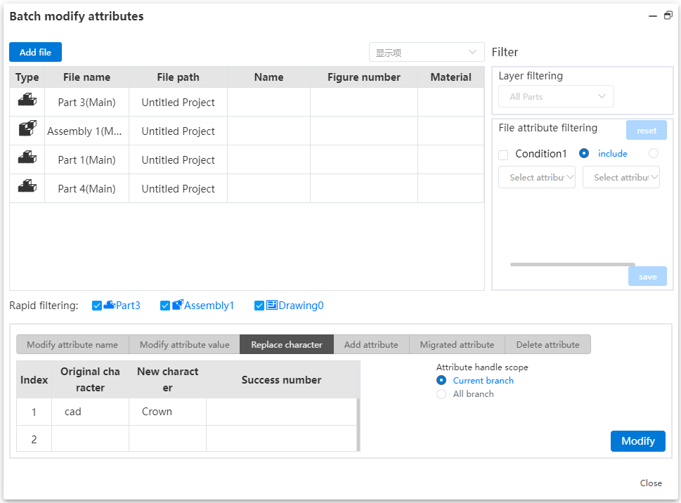
Click the "Batch Modify Properties" icon to enter the batch modify properties dialog box, and the document list shows all the parts contained in the current document.
Click Level Filter, select the level type, and filter the document list by level.
Click the "Add File" option to add additional parts by selecting the appropriate add method.
Click the "Display item" drop-down menu to make explicit and implicit Settings for the document list display item.
Quick filter, by checking the corresponding file type to make the files in the list appear and hide.
Attribute filtering, select the attribute name and attribute content, and filter the document list according to the attribute.
Change the property name, modify the property name. Select the original property name of the model through the drop-down menu, enter the new property name, and set the property processing range by clicking.
Change the property value to make modifications to the property value. Fill in the original property value and the new property value, and set the property processing range by clicking.
Character replacement: Replace some characters in the attribute value. Click the cell, fill in the original string with the new string, and set the property processing range by clicking.
Property transfer, copy the property to the branch, click the cell to fill in the property name, through the click box to select the processing mode, moving direction, processing range.
Add properties, add properties for parts in batches, enter the property name and property value in the table, set the property processing range by clicking.
Delete properties, delete properties for parts in batches, click the cell to fill in the property name, select the processing method and processing range through the click box.
# General
# Variable
# Variable interaction optimization
Re-structured variable interface. You can now create and edit variables directly within a table-like interface. The current variable interface is more streamlined and intuitive, with advanced and user-friendly interaction methods. It also supports more variable management functions, resulting in significant improvements in both interactivity and functionality.
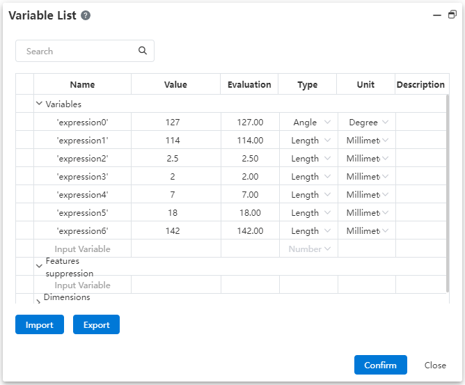
Content Description:
Name:Prohibit input of text in the format of @, such as D1@1, where neither characters should precede or follow the @ symbol.
Value:Dropdown to display variable and function options, with secondary menu options shown as well. You can also input numerical values, calculation formulas, or pick dimensions from the viewport.
Evaluation:Automatically calculate estimated value based on the given value, which is non-editable.
Select variable type or unit, with the default type being numeric.
Description:Optional field.
Interactive description:
Save the variable directly after input is completed.
Search: Allows searching through all items in variable management.
Import/Export:Only variables can be imported and exported.
Click on the cell in the first column of the variable to select it, then delete the variable via the right-click menu.
# IF Function
When creating variables, add an IF condition function. You can use this function to make your model more "intelligent", allowing it to switch to different styles based on defined conditions.
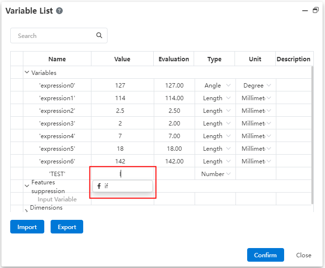
Variables support the use of the IF function, with the syntax being IF(Condition, Result 1, Result 2). The condition is an expression, and Result 1 is the output when the condition is true, while Result 2 is the output when the condition is false.
In the IF function, the condition can be a logical expression or a combination of multiple expressions, which can be constructed using operators like 'and', 'or', etc. It can also be nested for more complex conditions.
The IF function can control dimensions based on conditions, such as A = IF('D1@Sketch1' > 30, 10, 8), which means that if the value of D1 in Sketch1 is greater than 30, the variable A takes a value of 10; otherwise, it takes a value of 8.
In assemblies, you can use the IF function to control features. For example, you can control the number or spacing of an array based on part dimensions.
# Dimensions management
# Sketch dimension ID
Sketch dimension numbering: Assign a unique identifier to each dimension in a sketch for better organization. You can customize the names yourself, and they can be managed and modified uniformly within the Variable Management interface.
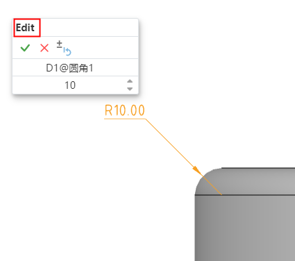
When creating sketch dimensions, assign a unique number to each one. This number will be displayed when creating, editing sketch dimensions, and viewing dimension properties.
# Feature dimension ID
Record the dimensions of all features in parts and assemblies. You can customize the names yourself, and they can be managed and modified uniformly within the Variable Management interface.
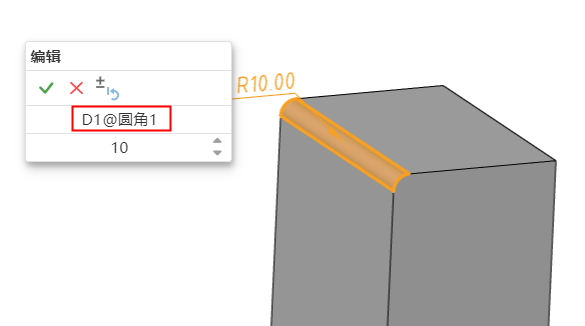
When you double-click a feature in the Feature List, the associated dimensions will be displayed in the viewport. Clicking on the dimension value will only modify the dimension without showing the number. Double-clicking will allow you to modify both the dimension and the number.
# Dimensions management
In the Variable Management, all dimensions are displayed and managed uniformly. You can view almost all dimension parameters of the model intuitively in this interface and make modifications and management in a unified manner.

Dimensions Name:In variable management, you can edit and change the dimension numbers, but only the number itself can be modified, not the suffix. The changes made will be consistent with the dimensions in the features.
Number:When editing and modifying in variable management, if the dimension uses a variable expression, the expression will be displayed. If it's a constant expression, only the final numerical value will be shown.
Evaluation:In variable management, when the dimension is based on a calculation result, the displayed value is read-only and cannot be edited directly. You would need to edit the underlying expressions or variables to change the value.
Type:In variable management, dimensions are displayed based on their type, such as length for distances, angle for rotations, count for arrays, and percentage as a numerical value. The percentages are read-only and cannot be edited directly. Any changes to these would require modifying the underlying parameters or equations that define them.
Unit:Can be changed to the supported unit of the current type.
In size management, the dimensions or items that cannot be edited are set to gray.
Edit the sketch or feature to modify the size value in the list automatically updated, vice versa in the list to modify the value can also drive the feature update.
Document dimensions cannot be deleted. Dimensions created in assembly can be deleted. Editing related functions are described below.
# Edit dimensions in assembly
In the dimensions list of the assembly document, you can associate parts, variables in the assembly, or dimensions with existing dimensions, driven by the same data. In this way, you can directly modify the parameters of the features of the parts in the assembly through the variable management function, and improve the efficiency of association modeling.
Open variable management in assembly, display the size of match, feature and sketch in the current document in the size list.
Click the name box in the blank column, you can pick up a size in the viewport, and automatically fill the number of the size into the variable name.
After confirming the name, press enter to focus on the value input box, the value supports the input item:
- Select assembly variables and functions from the drop-down list
- Enter the value, calculation formula
- The dimension value of any part or assembly in the current document cannot be the same as the dimension value in the name. It can be entered or picked up, and the input rules are consistent with the name; Pick can be picked up in the viewport, or click the size name in the size list
- Dimensions also support calculations, such as' d1@distance 1 '+' d1@distance 1 @part 1 '
Automatically calculate and fill estimates based on the picked value type.
The type and unit are automatically filled according to the picked variable name size, the type can be modified to a number but cannot switch the Angle or length, such as the name is the length size, the value is the Angle size, the created variable is still the length, only the value of the Angle size is taken.
After the size is created and you click OK, the size picked up at the name will be automatically driven by the value set in size management.
When the dimension of a part refers to the value or variable of another part, that dimension is an external reference status in the document.
Automatically create a new line of blank table after adding the dimensions; The created dimension right button shows the delete function, click to delete the dimension.
Example Scenario 1:Part size is set as variable in assembly
There is dimension [D1@ sketch 1=20mm] in part P1, the size list is opened in assembly, and the name picks up the size
Enter 30 in the value, OK, the size becomes 30 in the viewport, and is displayed as variable style
In the assembly, the value can be modified by editing the size or in the size list, which automatically becomes a constant when the size is deleted from the size list
In parts, editing the dimension shows as external reference cannot be edited; The dimensions are removed and then go back to the assembly to open variable management, indicating that the name of the variable is missing
Delete the association effect, D1@stretch 1 in the part completes the above operation, when there is a D1@stretch 1 in the part after deleting the stretch, creating the stretch, renaming the feature, the size is automatically used in the assembly
Suppression of features, sketches and rollback in the part do not affect the variables in the assembly
In the above piece, change the input value to the variable A=25 already in the assembly, and the variable created at this time is:

Example Scenario 2:The part variable is referenced by another part
Part 1 has variable A=25, dimension D1=A, and part 2 has dimension D2=15mm
Open the list of dimensions in assembly, name picks up D2, value picks up D1, and the variable created is:
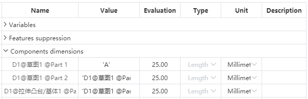
The dimensions in part 2 are now associated with D1 in part 1, and D2 will always hold the same value even if D1 is changed to a constant
After modifying the variable in part 1, you must first open the assembly document for part 2 to update automatically, and directly open part 2 does not update
The suppression and rollback operations in Part 1 do not affect the variables in the assembly
Delete the size in the part, and then return to the assembly to open the variable management, prompting the corresponding name or value is lost, can be re-edited
Delete this item from the size list of assembly, and the value of D2 size in Part 2 becomes a constant value
Edit D2 in Part 2 prompt that external reference cannot edit, deleting this dimension has no effect on other documents
In the above condition, when the variables are created interchangeably D1 and D2, then D1 in Part 1 no longer refers to the variables in the original document and is controlled by D2 in Part 2
# Edit dimensions in Parts
In the dimension list of the part document, the dimension of the part can be associated with an existing dimension or variable, driven by the same data. Improve the efficiency of setting the correlation reference between dimensions.
Example Scenario 1:Feature size modification
There are dimensions [D1@ sketch 1=20mm] in part P1, and the list of dimensions is opened in part
Enter 30 in the value of the item, OK, the size in the viewport becomes 30, and the feature is automatically updated
This size is still a constant, and it will be updated here when the value is modified by editing the feature
In the above, change the input value to the variable A=25 already in the part, and the dimensions change to the variable style
Example Scenario 2:Feature size association
Among the parts are: D1@ stretch boss 1=25, D1@ sketch =A, create stretch cut 1=10mm
Open the list of dimensions and in the value of the D2 item set to: D1@stretch boss 1-10
The valuation is 15, click OK and then the stretch cut will update automatically
After modifying the value of stretch boss 1, stretch excise 1 is also automatically updated
Edit stretch cut 1 and the depth value is displayed as in the list
After deleting stretch 1 (assuming it is not associated with deleting stretch excision), go back to the size list and indicate that the value is missing and you can edit the pick again
Delete and then undo the rollback size list will automatically return to normal state
# Features suppression
In a part or assembly document, the suppression of features can be controlled by equations. This function, combined with the function of condition function, can be more flexible to control the content of the model, such as according to the size of the different size can control the effect of different features in the model.
In the part document, select the "Feature suppression" option in variable management.
Feature:You can enter the feature name or pick up the feature in the part document
- The reference plane, origin, size of the document can not be picked up, the center of mass, sketch, feature, etc. can be picked up, and the feature can not be picked up when it is in the rollback state
- It can be picked up in the viewport or feature list, only the existing feature can be input, such as stretch 1, and the feature will be automatically associated after input
- The feature is renamed and automatically updated in the table; Features are deleted, automatically deleted from the table; The table is not affected when the feature is rolled back
- Automatically focus to the next cell after picking up the feature
Number:Select add equation for this feature, autofocus to note after input
- Supported types are consistent with variables and dimensions
- Add two options to variables: Suppress and unsuppress
Evaluation:Returns the status or value of the current feature. Cannot be edited here, only displayed. Suppress or unsuppress only takes effect on features, not numerical values.
Type、Unit gray unavailable.
Note:Select the field, press enter to complete the creation of the current feature equation and automatically focus to the next line.
Function effect:
- The suppression effect is consistent with the feature right-click suppression function, the parent feature is suppressed in the equation and the child feature follows the suppression
- By the same token, no matter what the state is before picking up the feature, the state of de-inhibition is maintained after creating the equation
- When the feature changes from suppressed state to uninhibited state, the feature and its parent feature automatically become uninhibited state, and the child feature is still suppressed state, and you can cancel the inhibition by right-clicking
After a feature is suppressed or uninhibited in the list, the suppression-related function buttons are no longer displayed when the feature is right-clicked
- The feature creates an equation, remains in the current state after deleting the equation, and restores the suppressor function button when right-clicking
Add or unsuppress the feature in the list, and then delete the feature to open the list, indicating that the feature name is lost, you can pick up the feature again.
Example:
Base level 1= suppressed: Base level 1 is always suppressed
Stretch excision 1=IF (' D1@ stretch boss 1 '< 30, inhibit, uninhibit) : when the depth of stretch boss 1 is less than 30mm, inhibit stretch excision 1, cancel inhibition when greater than or equal to 30. Stretch excise 1 will follow the depth of stretch boss 1 to determine the suppression state.
# Grouping of features
In parts/assembly documents, you can group things like features into folders. Achieve the classification management of features and other content to improve the legibility of the content.
Create folder:In the parts/assembly/assembly Topdown environment, right-click the features of the feature panel, and the [Create new folder] command is displayed in the right-click menu. Click the "Create New Folder" command. Create a folder, and place the feature of the right click inside the folder.
- Support what goes into the folder
| Contents | Instructions |
|---|---|
| Part CharacteristicsAssembly features | Includes part characteristics, assembly characteristics, assembly Topdown environment edit parts characteristics."Three default datum, origin, Center of mass" cannot be put into the folder.The order that contains the features of the parent-child relationship needs to be maintained. |
| Part Geometry | Including solids, surfaces, curves, grids.The same type of geometry can create folders for management, different types of geometry can not be placed in the same folder.The number of geometers in the folder is displayed after the folder name. For example, (2) indicates that there are two geometers in the folder. The number is not displayed when the folder is renamed. |
| Assembly parts | Place the parts instances of the same level in the folder, does not affect the actual hierarchy of the parts, only do classification. |
| Assembly fit | Fit can be placed in a folder. |
Features that have a parent-child relationship need to maintain a sequential relationship whether they are in a folder or not.
Manual grouping of weldment cut lists is prohibited.
# Click Pick Up
You can pick up the line in the dialog box of the pick point, and automatically judge and fill the point according to the pick position.
When the dialog box can pick up only one point, the mouse on the line will be highlighted, click to automatically fill the closest endpoint or midpoint from the click position.
Support for picking up lines: sketch (2D, 3D) and solid lines, curves, arc lines, three-dimensional curves and other lines are not closed (with endpoints), after picking up the effect of filling and preview are points.
When picking up curves (spline curves, arcs, three-dimensional curves, etc.), the point is calculated by the linear distance between the click position and the point.
Lines that do not support closure include circles, ellipses, closed splines, etc.
# Animation
# Editable
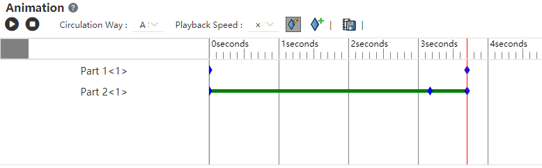
Mouse locate at the existing keyframe, drag and drop the part, you can edit the position of the part in this keyframe. This greatly improves the ease of use for creating and editing animations, even if you do not drag and drop the part once, you can adjust and modify it repeatedly in this keyframe to achieve the most ideal effect.