# Assembly
# Mate
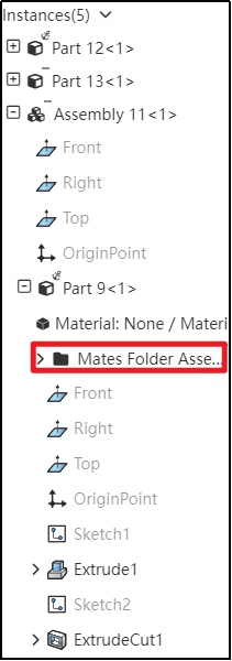
# Mate Folders
Within the Assembly Features panel, expand the components to view their mate folders, allowing you to easily see which mates have been added for each component in the parent assembly.
# Edit Mate Optimization
When editing a mate without modifying any parameters, after clicking 'OK,' no prompts will appear again. This optimization improves the user interaction experience."。
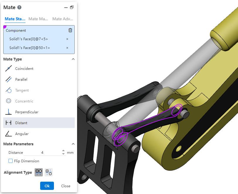
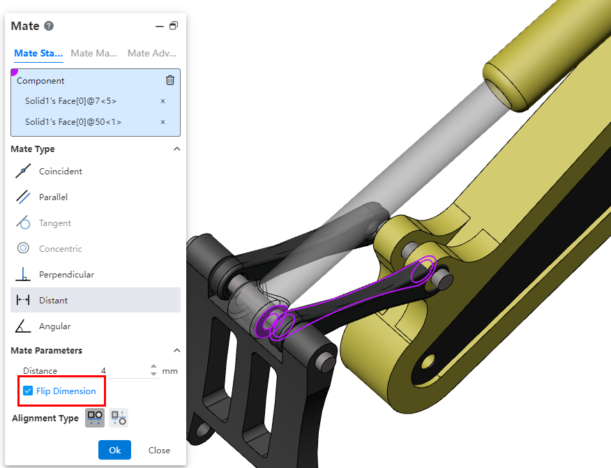
# Reversing Dimensions
When adjusting the numerical direction of mating parameters, use the 'Reversing Dimensions' feature to control their orientation.。
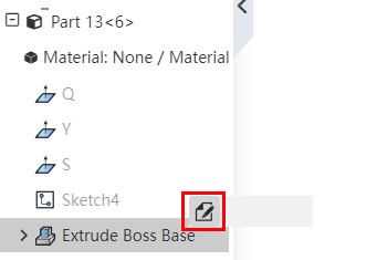
# Editing Features
In an assembly, right-clicking on a part's feature and selecting 'Edit Features' allows you to directly enter the editing state of the part and opens the 'Edit Features' dialog box. This function also applies to component sketches.
# Translate/Rotate
In the assembly, you can quickly display the triad of components and use the triad to translate/rotate components.
Method of Use:
1) Open 'System Settings - System Options - Assembly'.
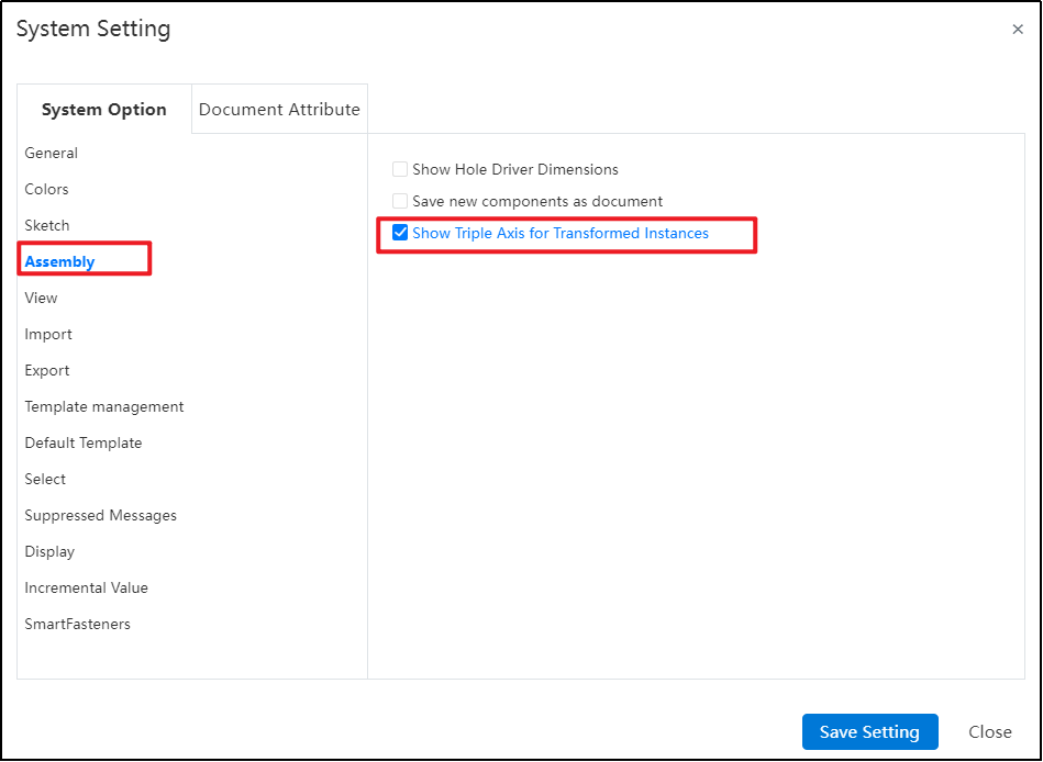
2) Check 'Show Triad for Transformable Instances'.
3) Open the assembly document.
4) In the Feature panel, click the component instance you want to move.
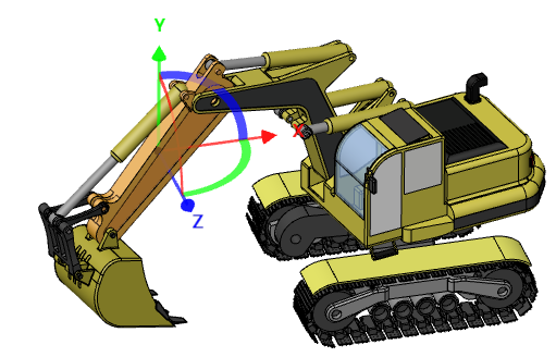
5) The selected instance will automatically display a triad. Drag the triad to move or rotate the component instance.
# Components Preview Window
A new 'Components Preview Window' feature has been added, enabling you to view selected components within the window while working in the Assembly Document without needing to open a separate document.

Using the Components Preview Window:
1) First, select the component instance you want to view in the viewport or Feature panel.
2) Next, click on the "Components Preview Window" command.
3) The selected component will appear in a split-screen window on the right side of your screen for previewing.
4) You can modify the display properties of the component within the assembly document and also synchronize the views between the preview window and the main assembly view.
5) Click to exit preview and end the viewing.
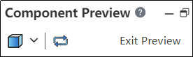
The Explanation of Dialog Box Controls:
Set the display style of the current preview component in the main assembly window.
Synchronized Views: Click this option to make the view of the main assembly window and preview window synchronized.。
# Inserting Component Rotation
During the insertion of components, the system supports displaying a quick menu for rotating the component, which makes it convenient to set its direction.
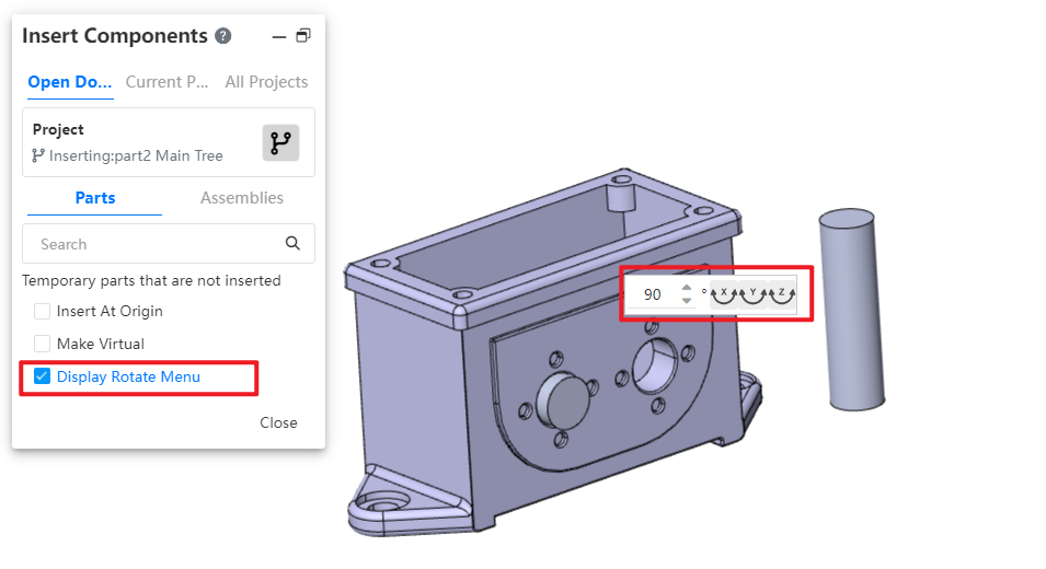
Usage Instructions:
1) Open the Insert Part or Assembly command.
2) Activate the "Show Rotation Menu" option.
3) Select the component you wish to insert.
4) Position your mouse in the viewport to display the rotation features' shortcut menu.
5) Input the desired rotation angle.
6) Click the XYZ button; the component will rotate around the corresponding axis by the entered angle.
7) Additionally, press the Tab shortcut key to rotate the component 90° around the Y-axis.
8) Click in the viewport to insert the selected component.
# Feature Adaptation
The following functionalities are now adapted to assembly documents and can be used in assembly document.
The "point-normal" type of reference plane supports the option of "percentage of curve length," allowing you to control the generation position of the reference plane by specifying a percentage on the curve.
Reference Lines: Added "Angle Bisector, Tangent to Curve, Point and Straight Line" Types.
To learn more about the features, please refer to the corresponding commands in the part module user manual.
# Disassembling Sub-Assemblies
Added: New Function – Disassembling Sub-Assemblies.
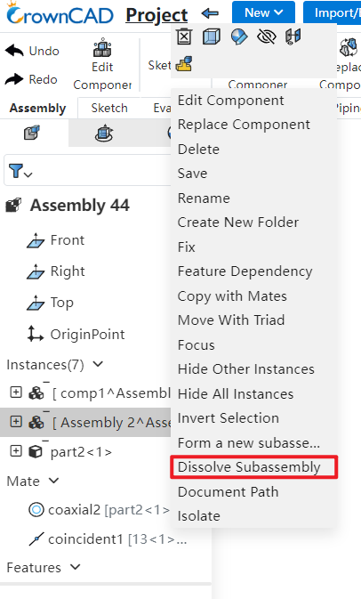
Usage Instructions:
1) Right-click on the sub-assembly you want to disassemble in the FeatureManager panel.
2) Click on the 'Dissemble SubAssembly' option.
3) If there are virtual components or features that cannot be preserved, a system prompt will appear.
4) Upon confirmation, the sub-assembly will be disassembled.
# Show Hidden Parts
Enhancement of the 'Display Hidden Parts' Feature: Now Supports Box Selection for Efficient Batch Component Selection.
Method of Use:
1) Click on the "Display Hidden Parts" command to activate the functionality.
2) In the viewport, draw a bounding box around the components you want to display.
3) Use the "Undo" button to remove any unintended selections from your current selection set.
4) Finally, click the "Exit Show-Hide" button to complete the operation and return to normal viewing mode.
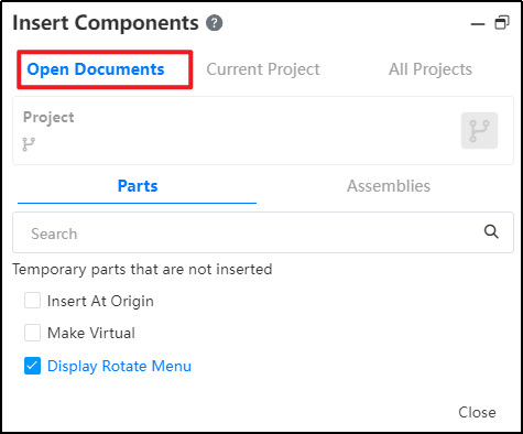
# Insert Components
The "Insert Parts or Assembly" function has added an "Open Document" page, allowing users to quickly insert open documents from the current project within it.
# Mirror Components/Component Patten
Mirror or array-generated components can be mated with other components, improving the flexibility of adding mating in assemblies.
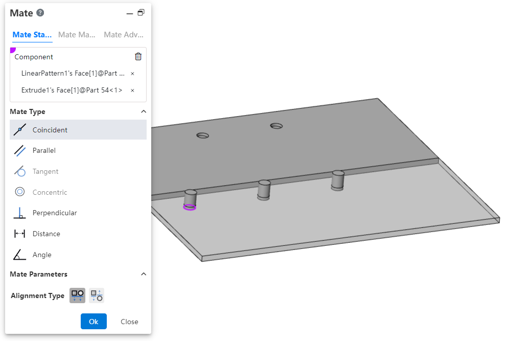
Note: Curve arrays and array-driven array instances are currently unsupported for this feature.
# Flexible Assembly
Added a new Flexible Assembly feature, allowing the movement of individual components within subassemblies in the main assembly.
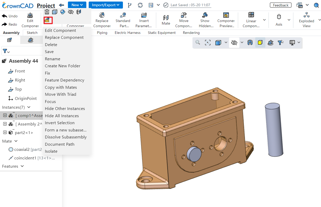
Usage Instructions:
1) Right-click on the subsystem containing the components you want to move.
2) Click "Make Subassembly Flexible."
3) Drag the components within the flexible subsystem; they can move independently.
Notes:
Components will move according to the existing constraints when dragged.
Adjusting positions within a flexible subsystem does not affect the original component locations in the source document.
Right-click the subsystem again to restore rigidity, reverting components to their original positions.
# Display Component Materials
Within the assembly instance list, expanding a component's hierarchy lets you view its material attributes.
