# Drawing
# Model Items
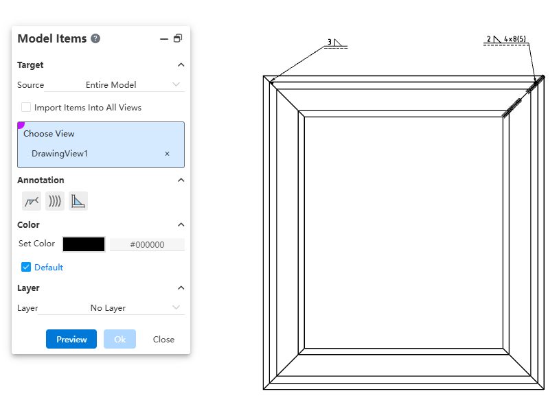
Added the model project feature, supporting the insertion of annotations corresponding to weld features from 3D model files into engineering drawings.
Dialog Box Control Instructions:
Source: Controls the source of the project. Options include "Selected Features," "Entire Model," "Selected Components," or "Assembly Only."
Insert Project into All Views: Controls whether the project is inserted into all views on the drawing. When selected, you can insert the model project into all views without manually selecting target views.
Target View: Controls which view the model project is inserted into. The project will be inserted into the selected view.
Annotation Type: Controls the type of annotation to be inserted. By default, none are selected.
Color/Layer: Sets the color and layer for the inserted project.
How to use:
Activate the Model Project command.
Set the target for the project: choose the source and the target view where the project will be inserted.
Select the annotation types to insert, including welding symbols, worms (caterpillar), and end treatments.
Set the layer and color for the inserted project.
Click Preview to display the insertion effect of the configured model project.
Click OK to complete the insertion of the model project.
Note:
- After viewing the preview, any changes to settings will cause the preview to disappear. You must manually click the Preview button again to recalculate and display the updated preview.
# Liner Note Pattern
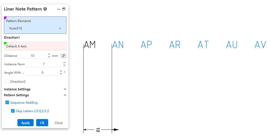
Added the linear array annotation command, which supports linear arraying existing annotations. This allows for quickly generating array annotations at specified locations, effectively improving drawing efficiency.

How to use:
Open the linear array annotation command.
Select the annotations to be arrayed.
Set the array direction parameters.
Set whether to array only the source or skip instances.
Set whether to apply sequence filling.
Click Apply/OK to complete the creation of the array annotation.
Dialog Box Control Instructions:
Elements to Array: Required. Select the annotation elements in the current drawing to be arrayed. Multiple selection and box selection are supported.
Direction 1 / Direction 2: Control the direction of the annotation array. Default is X-axis/Y-axis direction. You can manually set the array direction by picking two points or line elements. Direction 1 is required; Direction 2 can be optionally set, default is unchecked.
Distance: Enter the spacing between instances. The reverse button can change the array direction.
Number of Instances: Enter the number of instances.
Angle with X-axis: When no element is picked for direction, the array direction is set by rotating the current sketch’s X-axis counterclockwise by the specified angle.
Array Only Source: Default is unchecked. When checked, only two columns along the two straight-line directions are arrayed.
Skip Instances: Default is unchecked. When checked, select the annotations to skip in the array preview; these annotations will not be generated.
Sequence Fill: Controls whether sequence filling is applied to the selected annotations. Sequence filling only supports annotations with pure letters or pure numbers in a single direction, such as "AA" or "1". Default is unchecked; when checked, sequence filling is automatically applied.
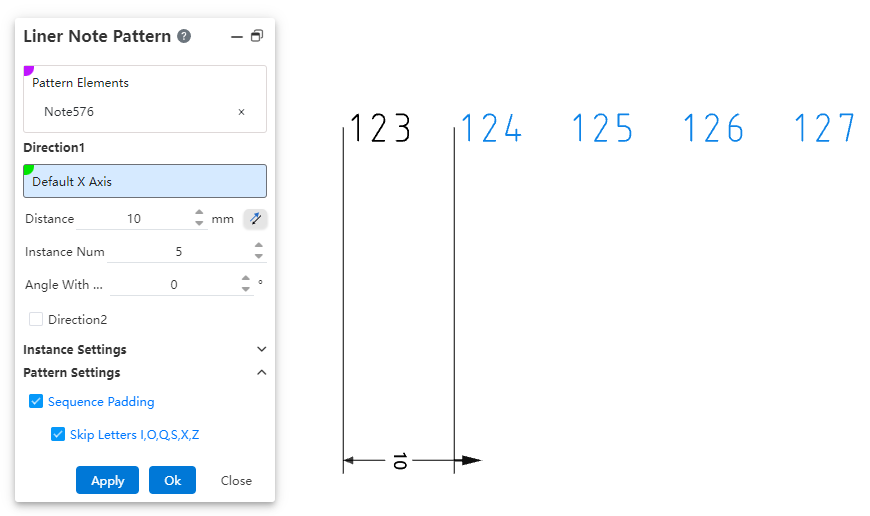
- Skip letters I, O, Q, S, X, Z: This option appears only when "Sequence Fill" is checked, and is selected by default. When checked, sequence filling will automatically skip the letters I, O, Q, S, X, and Z.
Note:
- The array source annotation and each of the generated annotations in the array are independent of one another. Each annotation is a standalone, independent entity without positional constraints, allowing individual editing, deletion, and repositioning.
# Circular Note Pattern
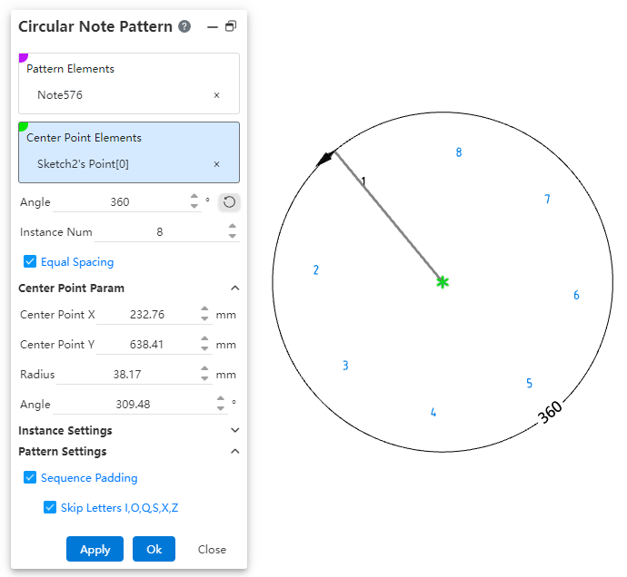
Added the circular array annotation command, which supports circular arraying existing annotations. This allows for quickly generating array annotations at specified locations, effectively improving drawing efficiency.
How to use:
Open the circular array annotation command.
Select the annotations to be arrayed.
Pick the center point of the array.
Set the array angle, number of instances, and center point parameters.
Set whether to array only the source or skip instances.
Set whether to apply sequence filling.
Click Apply/OK to complete the creation of the array annotation.
Dialog Box Control Instructions:
Elements to Array: Required. Select the annotation elements in the current drawing to be arrayed. Multiple selection and box selection are supported.
Center Point: Controls the center point of the annotation array. Default is the drawing origin. Supports manually setting the array center point by picking a point element.
Angle: Controls the array angle, used in conjunction with the "Equal Spacing" option. Supports dragging the handle to adjust the angle.
Number of Instances: Controls the number of array instances.
Equal Spacing: Controls whether the input angle represents the total array angle or the spacing angle.
Checked (Default): The input angle is the total array angle.
Unchecked: The input angle is the spacing angle between array instances.
Center Point X/Y Coordinates: Controls the X/Y coordinates of the center point relative to the drawing origin. Displays the current center point coordinates by default and supports manual input, including positive, negative numbers, and zero.
Radius: Controls the distance from the center point to the annotation source. Input range: ≥ 0.00001.
Angle: Controls the angle between the line from the center point to the annotation source and the X-axis of the drawing. Supported input range: [0°, 360°].
Array Only Source: Default is unchecked. When checked, only two columns along the two straight-line directions are arrayed.
Skip Instances: Default is unchecked. When checked, select the annotations to skip in the array preview; these annotations will not be generated.
Sequence Fill: Controls whether sequence filling is applied to the selected annotations. Sequence filling only supports annotations with pure letters or pure numbers in a single direction, such as "AA" or "1". Default is unchecked; when checked, sequence filling is automatically applied.
Skip Letters I, O, Q, S, X, Z: This option appears only when "Sequence Fill" is checked and is selected by default. When checked, sequence filling will automatically skip the letters I, O, Q, S, X, and Z.
Note:
- The array source annotation and each of the generated annotations in the array are independent of one another. Each annotation is a standalone, independent entity without positional constraints, allowing individual editing, deletion, and repositioning.
# Title Block
Added the "Title Block Field" command, which supports setting title block annotations, enabling quick editing of title block text or modifying annotations within the drawing format without having to enter the drawing format.
How to use:
1) Enter the editing drawing format mode and click on the "Title Block Field" command to activate it.
2) Drag the rectangular hotspot area to adjust its size and position.
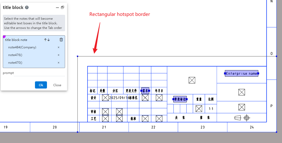
3) In the viewport, click on the annotation to set it as a title block annotation, and configure the prompt as needed.
4) Click OK to complete the creation of the title block feature.
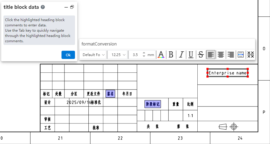
5) Enter the editing state for title block data by double-clicking the hotspot area, right-clicking the title block feature in the view panel and selecting "Insert Title Block Data," or right-clicking the hotspot area and selecting "Insert Title Block Data."
6) Click any title block annotation to edit the selected title block annotation.
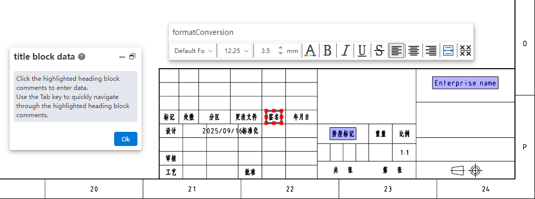
7) Press the Tab key to switch to the next title block annotation, or directly click on the title block annotation you want to modify to edit multiple title block annotations consecutively.
8) Click the OK button in the dialog box to complete this title block annotation editing session.
# Region Hatch Fill
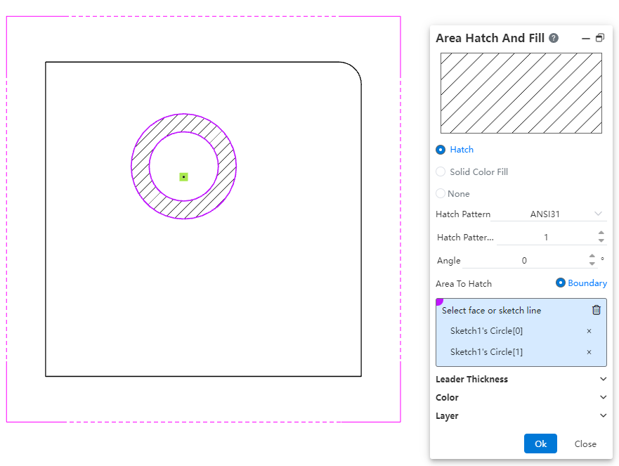
The region hatch command has been enhanced with additional hatch types and improved capabilities. It now supports picking sketch boundaries to fill hatching, and the range of model faces that can be filled has been expanded to include non-planar model faces.
How to use:
1) Open the region hatch command.
2) Select a single closed sketch boundary or a non-planar model face projection area.
3) Click OK to fill the region hatch within the closed sketch profile or selected model face area.
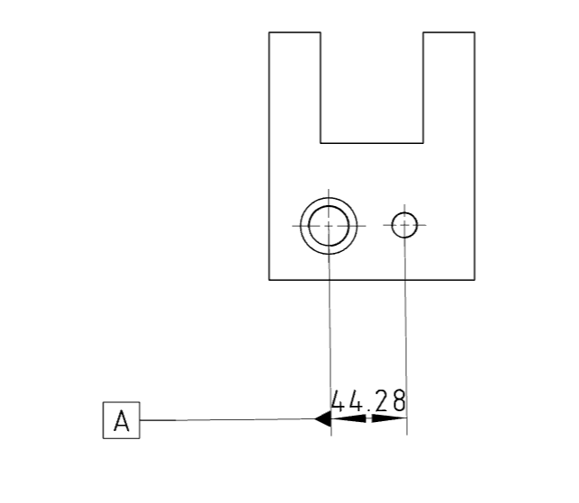
# Datum
Added the ability to pick dimension values when creating a datum. The datum created by snapping to dimension values is automatically merged with the dimension and aligned with the dimension line.
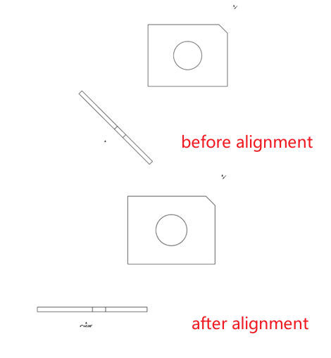
# Align Engineering Drawing Views
Added the feature to align engineering drawing views, supporting the alignment of auxiliary views, section views, and other views with angles to the engineering drawing views.
How to use:
1) Right-click the view you want to align.
2) Click on the "Align Engineering Drawing Views" dropdown menu, and select "Counterclockwise/ Clockwise Horizontal Alignment" to rotate the view to a horizontal alignment angle in the counterclockwise/clockwise direction.
3) Right-click the view that has been aligned.
4) Click on the "Align Engineering Drawing Views" dropdown menu, and select "Default Alignment" to restore the view to its default angle as it was when originally created.
Note:
The "Align Engineering Drawing Views" dropdown option is displayed only when right-clicking a view to set alignment.
Alignment can only be applied to section views, auxiliary views, and removed section views.