# Motion Analysis
# Motor
Support adding motors to drive components to move linearly or rotate.

How to use:
Open the Motion analysis and select the Motor
 command.
Choose the motor type according to your requirements.
Select the position where the motor will be added.
Choose the reference direction for motor rotation.
Select the component(s) that will move relatively during motor rotation.
Select the component(s) that will move relatively during motor rotation.
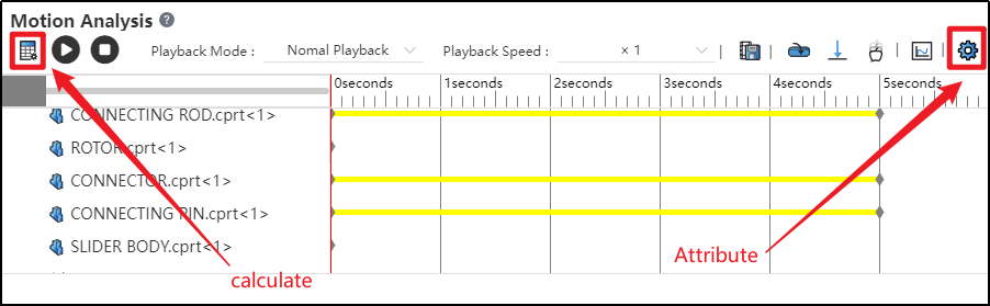
Click on the Motion Study Properties in the upper-right corner, select the solver, and then click Calculate in the upper-left corner.

After successful calculation, click "Play"
 to view the motion process.
Click the "Save" button at the bottom-right corner to save the motion study results.
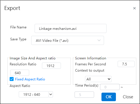
Click "Export"
 to export video files in different formats as needed.
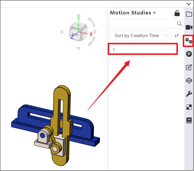
- Click on the Motion analysis list in the right sidebar to find the saved motion study.
Note: Currently, only constant-speed rotation or linear movement is supported. In future versions, variable speed, intermittent motion, and other motion types will be supported, which can be defined using functions and other methods.
Dialog Box Control Instructions:
Motor Type: Currently supports rotary motors and linear motors, with rotary motor as the default. Path motors will be supported in future versions.
Motor Position: The driven component that rotates or moves under the influence of the motor.
Motor Direction: The reference direction for motor motion. Users can choose clockwise or counterclockwise rotation as needed.
Motor Direction: The reference direction for motor motion. Users can choose clockwise or counterclockwise rotation as needed.
Speed: Set the motor's motion speed. Default speed is 100 RPM for rotary motors and 10 mm/s for linear motors. Input range: [0, 1e5].
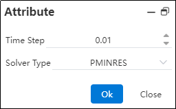
Time Step: The time interval for each calculation cycle used by the solver.
Solver Type: Different solvers with various computational methods and kernels.
# Force/Torque
Support adding forces/torques to components to simulate their motion under loading conditions.

How to use:
Open the Motion analysis and select the Force
 command.
Choose the type of external load to be applied according to your requirements.
Select the position and direction where the external load will be applied, as needed.
Choose whether the load is a single force or an interaction force, as required.
Set the force function type and the magnitude of the load. Click OK.
Click on the Motion Study Properties in the upper-right corner, select the solver, and then click Calculate in the upper-left corn.

After successful calculation, click "Play"
to view the motion process.Click the "Save" button at the bottom-right corner to save the motion study results.
Click "Export"
to export video files in different formats as needed.
Dialog Box Control Instructions:
Force Type: Choose between force or torque based on your requirements.
Position: Select the location where the external load will be applied, according to your needs.
Direction: After selecting the position, the system automatically displays the load direction using an arrow. You can adjust the load’s positive or negative direction as needed, or re-pick a geometric element to define the load direction.
Direction Type: Choose whether the load is a single-direction force or an interaction force based on your requirements. (External loads are typically single-direction forces; springs are interaction forces.)
Application Point: Select the point where the load will be applied, according to your needs.
Force Function: Currently supports constant, step, and harmonic force functions. Future versions will support segment, data point, expression, and custom function types. After selecting the function type, enter the load magnitude.
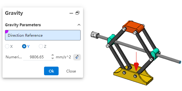
# Gravity
Support adding gravity to the entire assembly to simulate the effect of gravity on the motion simulation.
How to use:
Open the Motion analysis and click the Gravity
 command.
You can define the direction of gravitational acceleration using a 3D coordinate system, or select a geometric element as needed to define the direction.
Enter the acceleration value.
Click OK.
Note: Gravity is typically used in conjunction with motors, forces/torques. When defining gravity using a 3D coordinate system, there's no need to pick geometric elements.
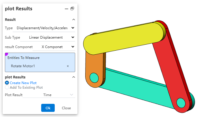
# Plot Results
Supports analyzing the motion process of Motion through diagrammatic calculation.

How to use:
Open Motion analysis and click on Result Diagram
 .
.Select the category to be analyzed according to your needs.
Determine the subcategory for analysis based on your requirements.
Specify the result component to be analyzed.
Pick a face, edge, vertex, or mate of the component.
Pick a face, edge, vertex, or mate of the component.
Select the dependent variable for the diagram result.
Click OK to generate the result diagram.
Note: Currently, only result diagrams for linear displacement, angular displacement, motor force, motor torque, etc., are supported. Support for all result diagrams will be gradually added in the future.
Dialog Box Control Instructions:
Category: Select either "Displacement/Velocity/Acceleration" or "Force".
Subcategory: The subcategories for "Displacement/Velocity/Acceleration" are "Linear Displacement" and "Angular Displacement"; the subcategories for "Force" are "Motor Force" and "Motor Torque".
Result Component: Specify the direction of the result component.
X/Y/Z Components: Represents the component values along the X/Y/Z axes.
Magnitude: The magnitude of the result can be resolved relative to the global coordinate system.
Select a face, edge, vertex, or mate of the component: Define the object for result diagram calculation.
Diagram Output Options: Specify the output settings for the result diagram.
Generate New Diagram: Creates a new diagram independent of existing results in the motion study.
Add to Existing Diagram: Adds the calculation results to an existing diagram, generating a multi-Y-axis curve.
Diagram Result Independent Variable: Specify the X-axis variable for the diagram result. Options include time, frame number, or a new result.