# Broken-Out Section
Supports the addition of a broken section view feature on an existing view, which opens up parts of the view.
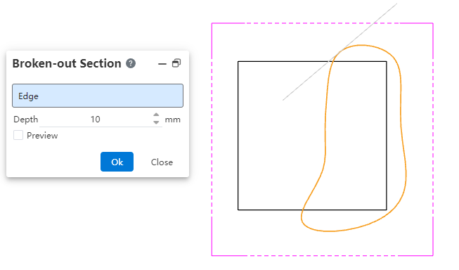
Click  on the toolbar to open the disconnected section view command dialog box, and its command interface is as shown in the following picture:

# Parameter Description
- Edge line: The depth of the plane on which the selected edge line is located is taken as the cutting depth.
Pick up a model edge line in the current view, requiring that the edge line is on a plane parallel to the projected plane of the current view.
- Depth: Define the depth of the cut.
- When picking up edges, this item shows the depth of the selected edges and cannot be modified.
- When the edge line is not picked up, the depth can be set by manually entering the value.
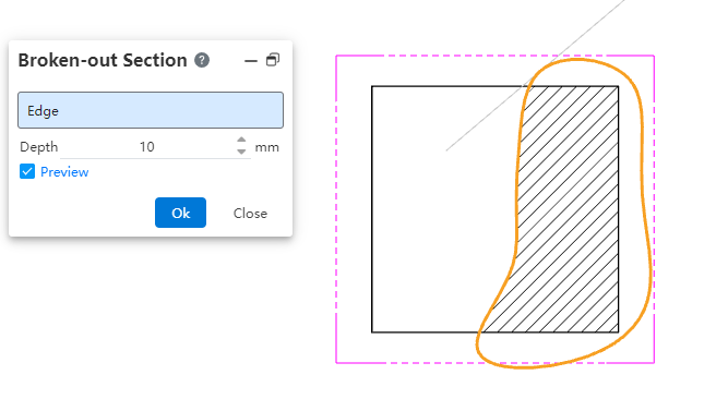
- Preview: Controls whether cutting preview, position and direction are displayed.
- Unchecked: Do not display the cutting preview and the cutting position and direction.
- Check this box to show the cutting preview and the cutting position and direction on the relevant view.
Note:
① Multiple "broken section view" features can be added to the same view and can be superimposed;
② The depth is calculated from the top of the uncut state model bounding box in the current range;
③ The cutting region is required to be a single closed loop region.
④ The sketch of the cutting area should belong to the view;
⑤ Supported views: model view, projection view, section view, auxiliary view;
⑥ Unsupported view: partial view, fracture view;
⑦ Elements displayed in the disconnected section view support normal dimensioned, annotated, part serial number, etc. Broken borders cannot be marked.
⑧ Due to re-editing operations such as model transformation and view Angle adjustment, when the broken section view cannot be correctly generated, the cutting effect of the viewport disappears, and the feature of the broken section view turns red to remind the user that there is a problem.
# Create a Broken-Out Section
- Draw the outline of the cut area
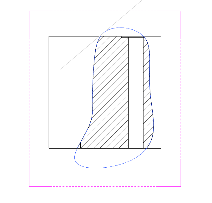
- Double-click on the view you want to create the disconnected cutaway view to enter the lock-focus state (the view border is shown in pink).

- Switch the toolbar to Sketch and draw the outline of the closed section with the Draw command. The outline drawn is the area to be cut.

- Execute the command:
Select the closed outline drawn in the previous step, then click on the command 【Broken Section View】 to bring up the command dialog box.
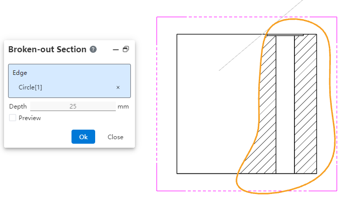
- Set the cutting depth
Confirm the depth of the cut by selecting the side line or entering the depth value directly.
- Finished creation
Click Preview to see the cutting position, the cutting direction; Click [OK] to finish the creation; Double-click the left button in the blank area of the drawing to exit the locked focus state.

Note: Before executing the "Broken Section View" command, please lock the focus view and select the cut outline sketch.
# Edit the Broken-Out Section
# Edit the Depth of the Cut
- Start editing
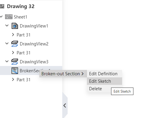
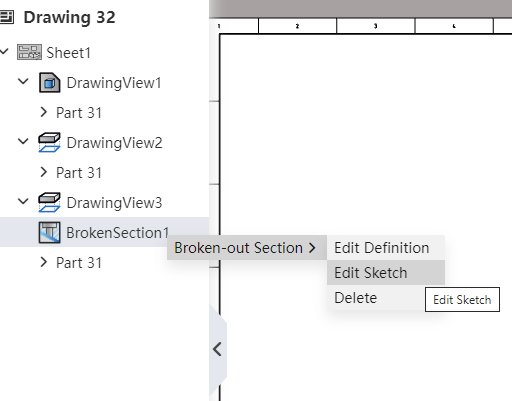
Right click on the "Broken Section View" feature in the feature panel and select "Edit Definition".
- Modify the depth
Reselect the edges in the dialog box or set the depth directly.
- Click OK to finish editing.
# Edit the Cutting Area
- Start editing
Right-click the "Broken Section View" feature in the feature panel and select "Edit Sketch" to enter the sketch editing state.
- Adjust Area Area
- To modify the zone:
Select the current area sketch, drag the control point or edge line to change the area, and select the sketch line when the modification is complete, making sure that the sketch lines that make up the area are selected and highlighted.
- Draw a new area:
Launch the desired sketch drawing command, draw a single closed area in the viewport, and select sketch lines when you're done, making sure the sketch lines that make up the area are selected and highlighted.
Note:
① Before exiting the sketch, be sure to check the sketch line that you want to use as an area.
- Exit Sketch
Click Exit Sketch to automatically determine if the selected outline sketch meets the requirements.
- End Edit

# Use Tips
- For simple sketches, you can pick up just one sketch line in the outline, and the system will automatically pick up other sketch lines connected to that sketch line to form a closed outline.
- For a complex sketch (such as one that contains multiple overlapping Outlines), the system may not be able to pick up the outline you need, at which point it is recommended that you pick up all sketch lines in the entire outline to ensure that the broken section view is contoured correctly.
← Break View Crop View →