# Model View
Model view generates a single view based on predefined viewing directions and scales. Steps to insert the model view into the project drawing:
- Click
 on Model view, pop out the Select Model command box,
- Create a blank project drawing, you can select the current project or all projects under the model to generate the project drawing.
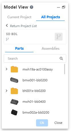
- According to the project drawing created directly by the model file, the model document is automatically linked in the list, and you can also re-select other model files.
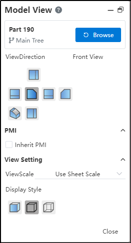
After selecting the model, click OK. The function box of selecting the view direction appears. After selecting the view direction, you can preview the corresponding view by placing the mouse in the viewport.
Select drawing scale, you can use the default drawing scale, or change to a custom scale.
Select a display style that supports "Color," "Eliminate Hidden Lines," and "Hidden Edge Visible" modes.
Click the mouse to place the view when it is in the desired position.
The resulting model view can be dragged to modify the position.
When you need to switch the view that generates other models, click the "Re-select" button to display the recently used model, continue to click the "Browse" button to select the model in the current project or another project.
Note:
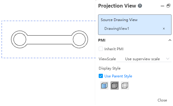
After placing the model view, the Projection view command will automatically start to facilitate the continuous creation of views.
To create a view with a custom perspective, you must first create a view. Then, click the created view and select the Custom View icon to modify the view perspective.
In the Custom View area, view names preceded by a Model Icon are defined in the 3D Model, while those without an icon are defined in the Drawing.
Views defined in the 3D Model cannot be deleted in the Model View Dialog Box of the Drawing.
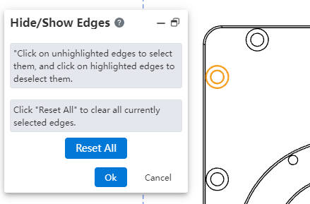
Right view blank space or right view model edge line, support to hide the model edge line in view.
- Both methods can hide the edge line, only the right view of the blank can be unhidden.
# Sheet Metal Plate Types
For parts that contain only one sheet metal model, you can create a model view of sheet metal plate types.
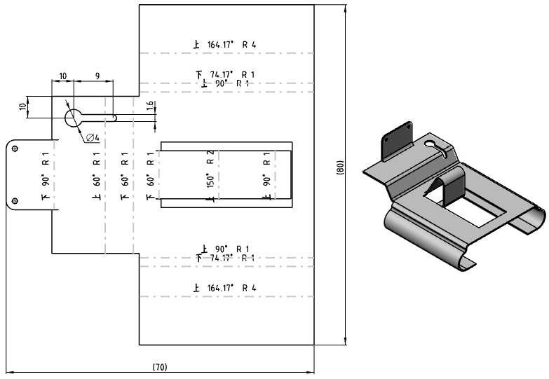
# How To Create
Create a model view of the sheet metal plate type by selecting the part that contains only one sheet metal model and checking the "Plate type" option.
# Parameter Description
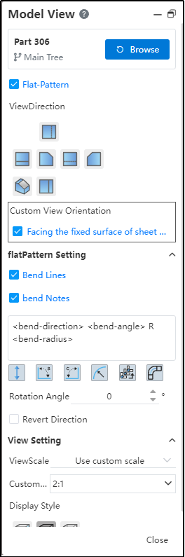
Plate Type: Check this to create a plate type view. Existing views do not allow this to be modified.
Face the sheet metal fixed surface: View direction Face the flat sheet metal. You can select another preset view direction or create a custom direction.
Bending line: Displays the sheet metal bending line in the view.
Bend Note: The parameters of the bend are displayed on the sheet metal bend line in the view.
Input box: Controls the display of the bend comment.
Parameter button: Used to quickly insert preset bending parameters into the input field.
| Icon | Parameters | Instructions | Key Words |
|---|---|---|---|
 | Bending direction | Bending direction relative to current viewing Angle: up, down | < bend-direction > |
 | Bend corner | Bend Angle | < bend-angle > |
 | Supplemental Angle | The supplementary corner of the bend corner | < bend-complementary-angle > |
 | Bend radius | Bend radius | < bend-radius > |
 | Bend order | Bending order | < bend-order > |
 | Bending coefficient | Bending coefficient | < bend-allowance > |
- Rotation Angle: Causes the sheet metal to rotate at a given Angle.
- Reverse direction: Reverse the reverse of the sheet metal projection, i.e., view the sheet metal from the other side.
# Assembly Exploded View
Select the assembly that contains "Explosion View" and check the "Explosion View" option to create a model view of the explosion.
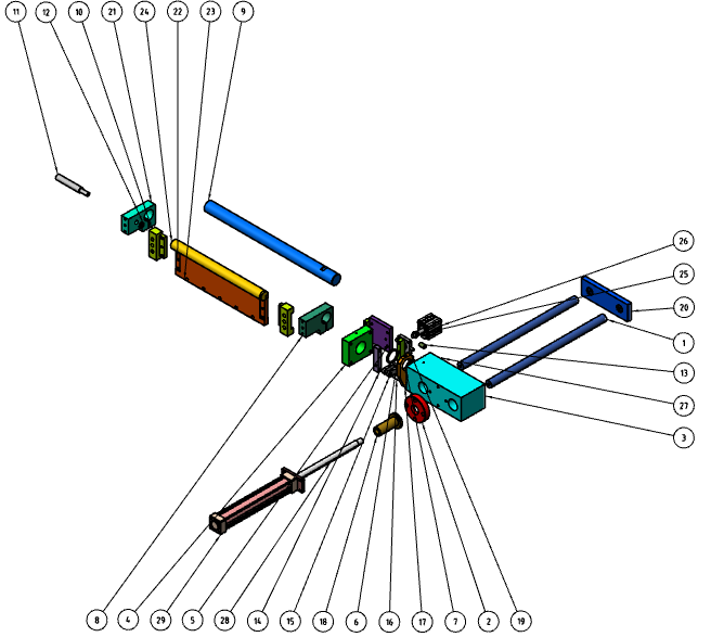
Select the assembly that has created an "Explosive view" and check the "Explosive View" option to create a model view with explosive content.
Note: The "Default Explosion View" that comes with the assembly cannot be referenced in the drawings, and the explosion view needs to be created manually.