# Insert Components
When a part (individual part or subassembly) is inserted into an assembly, the part file is linked to the assembly file and the part appears in the assembly; The data for the part also remains in the source part file. Any changes made to the parts file are updated in the assembly. Its command interface is shown in the image below:

The command is divided into 3 command pages: Open the document、Current items and All items, parts of different items can be inserted.
# Open Documents
Quickly insert open documents in the current project; the interface is as shown below:
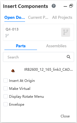
Note: Only display documents in the current browser tab.
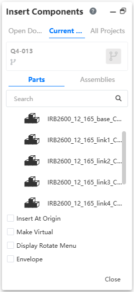
# Current Project
Select the part or assembly from all the documents in the current project to insert, the interface is as shown in the picture below:
# All Project
Select parts or assemblies from all projects created by users and shared projects to insert, as shown in the image below:
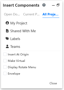
The controls are described as follows:
- My Project: Select a part or assembly from the project created by your current account.
- Shared with Me: You can select parts or assemblies from projects shared with other accounts.
- Tags: Select parts or assemblies in the project by label classification.
- Teams: Parts or assemblies can be selected from projects of different teams.
- Activities: Parts or assemblies can be selected from participating activities.
# Insert Example
- Click
 Insert Part or assembly in the assembly document;
 - Find the part or assembly you want to insert in the current project or all projects;
Note:
In the Insert parts or assembly screen, you can press ctrl or shift to select multiple parts
- Click
 to select which node or branch to insert the part;
 - Move the mouse to the viewport to preview the part or assembly;
Note:
Multiple selection, the selected parts appear in turn preview, by clicking the mouse to specify each part position
- Click anywhere in the viewport to place the part or assembly;
- Insert at the origin: when there are no parts in the assembly, open the [insert parts] command, the default check is "insert at the origin", and the check is automatically canceled after the first part is inserted; And insert the first part automatically add fixed constraints.

- When the inserted part is a blank document, it becomes a blank document when the mouse moves to the viewport to preview
 it, and then becomes a blank document after clicking to place it
  .
. - When previewing, when the origin in the assembly is highlighted, click the mouse to place, the origin of the part will coincide with the origin of the assembly.
- Insert at the origin: click preview after checking, and preview will appear where the origin of the part coincides with the origin of the assembly. Click at any position of the viewport, and the part will be placed at the origin.
Note:
- Hold down the left mouse button in the viewport to drag the part, you can change its position, if there is a mating relationship, the drag still maintains its mating relationship.
- If a part is modified in the part document, it will be updated in the assembly document in real time.
- When multiple parts are selected, the part of the branch is displayed in light gray and cannot be modified. Only the default branch of each part can be inserted.
# Virtual Parts
Virtual parts are saved in assembly documents and there are no separate parts or assembly files.
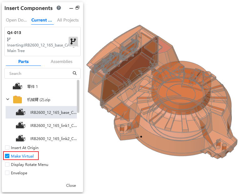
Usage Method 1- Insert new virtual parts:
1) Open the "Insert Part or Assembly" command.
2) Check "Make Virtual".
3) Select parts for insertion, and after insertion is virtual parts.
4) Edit virtual parts.
5) Right click virtual part - Save document.
6) Set the document name and path and click OK.
7) Save virtual parts as normal parts document.
Usage Method 2- Convert existing parts to virtual Parts:
1) Right-click an existing part in the assembly and click "Make Virtual" to convert it into a virtual part.
2) Edit the virtual part.
3) Right click virtual part - Save document.
4) Set the document name and path and click OK.
5) Save virtual parts as normal parts document.
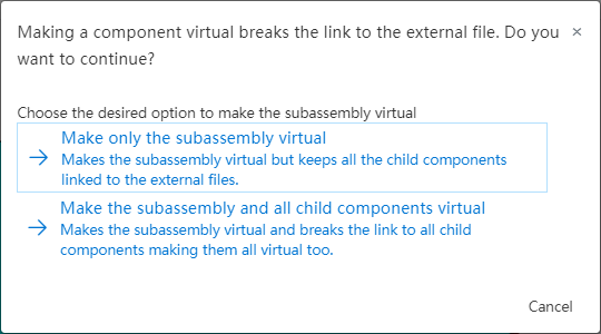
Instructions
When performing virtual operations on sub-assemblies, you can select "Make sub-assemblies virtual" or "sub-assemblies and all sub-components virtual".
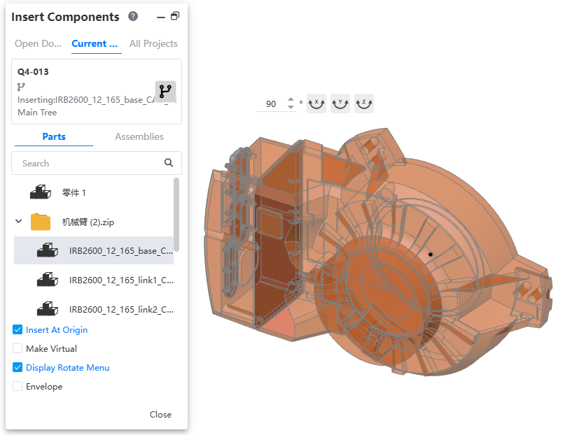
# Display Rotation Menu
When inserting components, the system supports displaying a rotation shortcut menu for parts to facilitate setting their orientations.
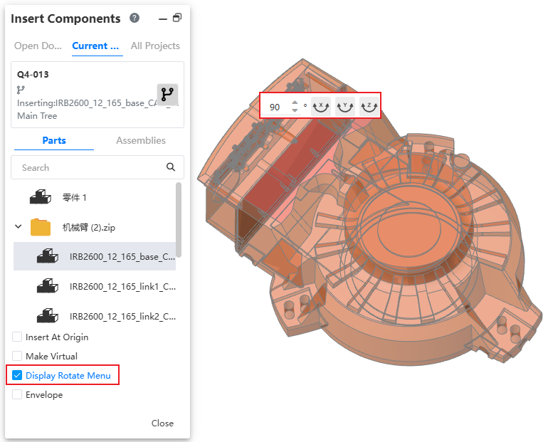
How to use:
1)Launch the 'Component Insertion' or 'Assembly Insertion' command.
2)Check the option to display the rotation menu.
3)Select the component(s) to be inserted.
4)Move your mouse to the viewport to display the rotation shortcut menu.
5)Enter the desired angle of rotation.
6)Click the XYZ buttons to rotate the component around the corresponding axis by the specified angle.
7)Press the Tab key to rotate the component 90 degrees around the Y-axis (an additional option).
8)Left-click in the viewport to insert the component.
# Envelope
Insert reference parts, such as assembly shells, into the assembly as Envelopes.
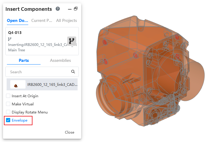
Usage:
Open the Insert Components command.
Check the Envelope option.
Select the parts to insert. Once inserted, they become Envelope parts.
Note 1: Envelopes do not appear in the Bill of Materials (BOM). The option to exclude them from the BOM is forced (checked) automatically.
Note 2: In a Drawing, you can edit the view, select View Properties, and control whether Envelopes are displayed.