# Mate
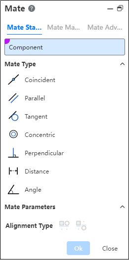
Mate commands are used to create coincident, parallel, perpendicular and other geometric relationships between assembly components, and to move components within their degrees of freedom. Its command interface is as follows:
# Mate Standard
Part: Select a point, line, or plane on two different parts.
Mate Type:
According to the different elements on the selected part, the system will filter out the applicable fit types. If there is more than one fit type, the first applicable fit type will be previewed by default. You can manually switch other fit types. The applicable element types for different fit types are as follows:
(1) Coincidences: points, lines, circles/arcs, curves, planes, cones, cylindrical, spherical, datum line, datum plane, coordinate system
(2) Parallel: straight, flat, conical, cylindrical, datum line, datum plane
(3) Tangency: straight, circular/circular arc, planar, conical, cylindrical, spherical
(4) Coaxial: point, line, conical, cylindrical, spherical
(5) Vertical: straight, planar, conical, cylindrical, datum line, datum plane
(6) Distance: point, line, plane, cone, cylindrical, datum line, datum plane
(7) Angles: straight, flat, conical, cylindrical, datum line, datum plane
Example:
Click
to Mate;
Select the graphic elements of the two parts in turn (in the absence of fixed constraints on the parts, the first part selected by default is displayed semi-transparently and its position changes according to the type of fit);
You can select the fit type and then the graphic element, or you can select the fit type first and then select the graphic element of the part;
According to the preview in the alignment type to choose whether to reverse;
Click "OK" to complete the operation.
Coordinate system instructions:
- Pick up the coordinate system with other elements, and coordinate the origin with other elements.
- Pick up two coordinate systems and display the Alignment Axis option when selecting the "Overlap" type. Check "Align Axes" so that the two coordinate systems coincide exactly.
# Mate Machine
# Gear Mate
Make the two parts rotate relative to each other around the selected shaft at a certain speed ratio.
- Parts: Select the cylinder, cone, shaft, straight/circular lines (including sketch lines, solid/surface edges) on two different parts.
- Ratio: Enter two values respectively, the ratio of the two numbers is the ratio of the rotation speed of the parts; The part with the larger value rotates slowly.
- Reverse: Control the direction of rotation of two parts.
- Unchecked by default, that is, relative rotation, such as one counterclockwise and the other clockwise.
- After it is checked, the parts turn in the same direction.
# Slot Mate
Allows you to fit the "cylinder/shaft" to the "straight/circular groove" or the groove to the groove, and supports the "free", "in the center of the groove", "percentage along the groove" and "distance along the groove" constraints.
- Parts: Select the elements on two different parts. The elements can be the following combination.
- Combination 1: Straight grooves or circular grooves + cylindrical surfaces.
- Combination 2: Straight grooves or circular grooves + reference shaft.
- Combination 3: Straight grooves or circular grooves + straight grooves or circular grooves.
- Constraint: Choose a positional constraint relationship between two elements. Take the cylinder and notch fit as an example:
- Freedom: The cylinder can move freely within the notch.
- Percentage along the notch: The percentage needs to be set and the cylinder can only be in a fixed position inside the notch.
- Distance along the notch: To set the distance, the cylinder can only be located in a fixed position inside the notch.
- Reverse: Control the direction of rotation of the two parts.
- Unchecked by default, that is, relative rotation, such as one counterclockwise and the other clockwise.
- After it is checked, the parts turn in the same direction.
# Hinge Mate
Components such as hinges for restraining the door.
Coaxial part element: Pick up the part element to which you want to add coaxial.
Coincident part element: Pick up the elements of the same part as the coaxial center and add a coincident fit.
The green range below indicates the combination of element types that support picking
Only elements with the same parts as the axis can be picked up
Limit Angle: Check this, select the plane belonging to the two parts respectively, set the Angle range of the two faces can be rotated relative to each other in the fit parameters.
The green range below indicates the combination of element types that support picking
Only elements with the same parts as the axis can be picked up
Alignment type: In the same direction or in the opposite direction, the button is available only after both coaxial and coax are selected.
Constraint effect: when the limit Angle is checked, the part becomes fully constrained, but it still supports rotation within the Angle range; When it is not checked, the effect is equivalent to adding coaxial and coincidence constraints.
# Mate Advanced
# Limit Distance/Angle
Allow parts to move within a certain numerical range of distance fit or Angle fit.
- Limit distance: The distance of the selected element in its current state.
- Maximum, minimum: The limit distance within the range within which the selected element can move.
Example: Set the limit distance of part 1 and part 2 to 40mm, the minimum value to 10mm, and the maximum value to 80mm, then the movable range is as follows.
# Symmetric
Make two solid elements symmetrical with respect to the datum or plane.
- How to use:Click Fit, switch to advanced fit, fit type select [symmetry].
- Symmetry plane:Select a plane or datum plane.
- Parts:Pick up two solid elements to fit.
- Alignment type:Controls the relative orientation of two elements, including alignment in the same direction and alignment in the opposite direction.
Instructions:
Two solid elements can belong to the same part or different parts.
When picking up two faces of the same part, the two faces must be parallel and the plane of symmetry should belong to the plane/datum of the other part.
The effect of symmetrical matching with the part elements is shown in the following figure:
# Profile Center
Align the geometric outline centers and completely define the parts.
Parts:Pick up sketch lines, edges, or solid faces of the two entities to fit.
- Element type: Closed loop sketch outline, solid edge line, solid face
- Outline type: full circle, rectangle, regular polygon, rectangle can be chamfered or rounded, face outline can contain cuts inside.
- When picking up solid edges, calculate the center of the contour based on the face on which the edges are located.
Fit parameters:Offset distance, lock rotation, direction.
Offset distance: Sets the offset distance between the centers of two Outlines.
Lock rotation: Select this option when selecting two circular contours to lock the rotation of the part.
Orientation: Use this feature to change the orientation of the part when selecting two non-circular Outlines.
Alignment Type:Controls the relative orientation of two elements, including the same alignment and reverse alignment.
Fit effect:After adding a fit, the contour centers of the two parts coincide, and the constraint state generates different fit effects according to different contour types and options.
When the circular outline is included, if "lock rotation" is checked, it will be completely constrained, and if it is not checked, it can be rotated around the center of the outline.
When circular contours are not included, the parts are fully bound.
# Width
Bind the parts between the two planes.
Width reference: Pick up two parallel or non-parallel faces.
Label reference: Pick two parallel or non-parallel faces, or a cylinder.
Constraint: Select the type of constraint, optionally "Center, free, percentage, size"
Center: The label overlaps with the width reference center.
Free: The position of the label in the width reference is not restricted and can be moved/rotated within the width reference.
Percentage: Limits the position of the label in the width reference by percentage.
Size: Limit the label by size to the location of the width reference.
Different combinations of width references and label references support different types of constraints:
Combinations | Width reference options | Label reference selection | Supported constraints |
1 | Two parallel faces | Two parallel faces | Center, freedom, percentage, size |
2 | Two parallel faces | Two non-parallel faces | Center |
3 | Two parallel faces | Cylindrical faces | Center, freedom, percentage, size |
4 | Two non-parallel faces | Two parallel faces | Center |
5 | Two non-parallel faces | Two non-parallel faces | Center, freedom, percentage, size |
6 | Two non-parallel faces | Cylindrical faces | Center |
7 | In combination 1/3/5, the width reference distance (or Angle) is less than or equal to the label reference distance (or Angle, cylinder diameter) | Center |
Coordination effect:
Center: Label reference the middle surface of the two planes, the axis of the cylinder and the middle surface of the width reference add the coincidence effect
Free: The label reference element is located at any position within the width reference range, and the label part moves/rotates within the width reference range, and stops when the move/rotation reaches the position where the element coincides or is tangent (the effect is similar to the restricted distance/Angle)
Scale: Similar to the constraint of notch scale in mechanical fit
Size: Combinations 1 and 3 show the distance value, combination 5 shows the Angle value, and the label reference is located at the size specified value
# View Mate
In the assembly document, select one or more elements to display a list of fits and edit fits. It is easy to visually see which fits exist in the element.
How to use:
1) In the viewport or instance list, select one or more parts, benchmarks, origin and other elements that can participate in the fit.
2) Right-click the "View Mate" function.
3) Click it to display the list of the selected elements, and the display status of the parts in the viewport changes.
Parts display status:
When the parts are compatible: all the existing top-level instances in the document automatically open the transparent function (the transparent function in the instance right click); Parts that are not included are automatically hidden
Parts that have been hidden before opening the match list will automatically become displayed and transparent when included, and remain hidden when not included
When the parts are not compatible: all parts automatically open the transparent function, and there are no more hidden parts
Match list operation:Click a match in the list with the left mouse button, and the corresponding element is highlighted in the viewport; Right click to display [edit], [delete] function, and the effect of the right click in the cooperate list of the two functions is consistent.
# Mates Folder
In the Assembly Featurespanel, by expanding a component, you can see its Mates Folder, which makes it easy to view all constraints added for that component within the parent assembly.
# Error Prompt
When incorrect matings exist in the assembly, you can click the prompt or the mating button in the mating list to view the list of incorrect matings.