# Line
Draw a line segment or multiple consecutive broken line segments in the sketch.
# Drawing Steps
1.Click Drawing Steps  to open the Polyline command box.
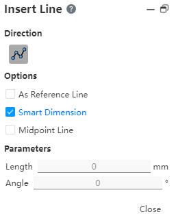
2.In the Insert Line command box, directions support drawing as is:
3.Under Options select:
As Guides: Draw guides.
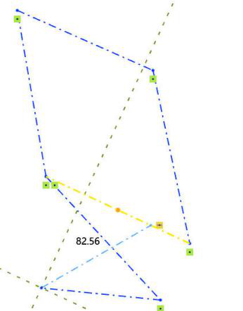
Create Size constraints: Add size constraints as you draw.
(Check Create size constraint, Enter value in Draw Parameter - Length, Enter to generate size annotation.)
Center line: Draw the center line. The first point clicked in the viewport after checking is the midpoint of the centerline, and the default is to return to the polyline command after the centerline is drawn.
4.Under Parameters, enter different parameters depending on the direction.
- When the direction is Angle, the Angle parameter can be entered before drawing.
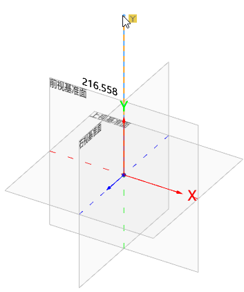
5.In the viewport area, the default drawing plane is XY plane. You can switch the drawing plane by pressing Tab. Line properties Click the line to display after the drawing is complete.
6.Example drawing method:
- Press Tab key to switch the drawing plane;
- Select a point as the end point, and then let go, the space control mark appears to help determine the orientation of line drawing;
- Move the mouse to another point and click, as another point of the line;
- During the drawing process, you can press the Tab key to switch the drawing plane at any time.
# Properties Box
1.Left click on the polyline in the viewport to display the polyline property box, as shown in the image below.
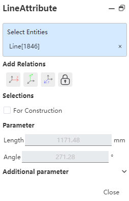
2.Existing constraints: Shows constraints that were added automatically during sketch drawing or generated using Add constraints. When an item is selected in the list, the corresponding element in the drawing area is highlighted.
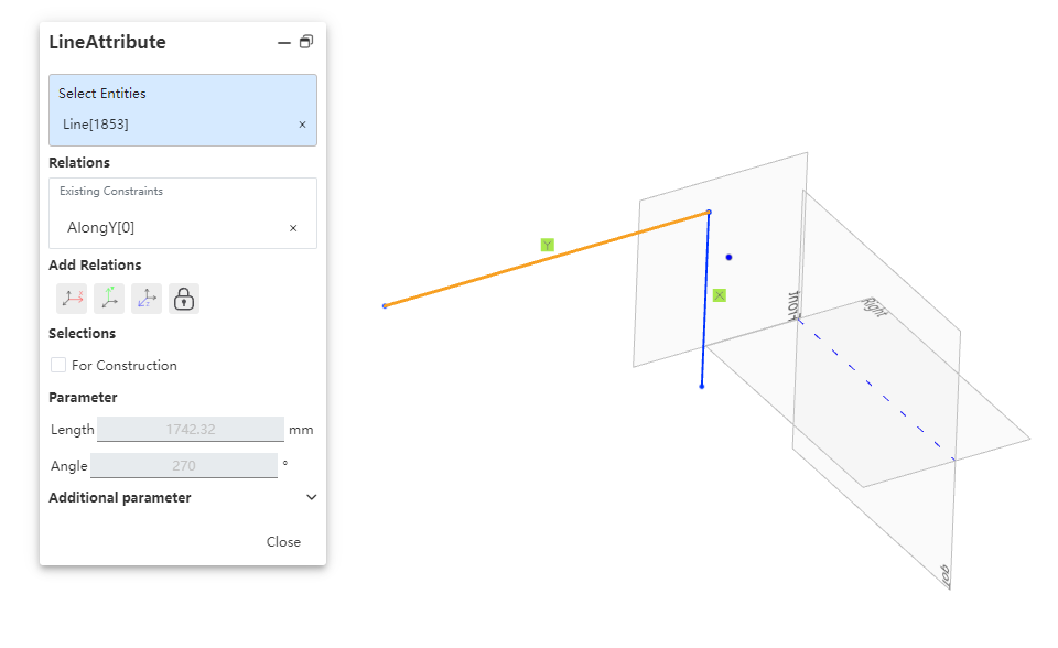
3.Add constraints: You can add constraints to the selected element. The list contains only the constraints that may be used by the selected element.
4.Option: As a Guide line - Convert sketch solid lines to guides.
5.Parameters: Cannot be changed. If the line has a size constraint, the relevant parameters are automatically updated when you change the parameters.
6.Additional parameters: Starting point X\Y\Z coordinates. Change requirements are consistent with parameter changes.
# Centerline
1)Click
2)Press the Tab key to switch drawing planes.
3)In the viewport, click sequentially to specify the endpoints of the line; the resulting line will be of reference type.
4)You can continuously draw multiple segments.

# Instructions for Use
1.The dotted orange line displayed during line segment creation is the guide line, marking the plane where the line segment is located.

2.Polyline - Arc function: After drawing the polyline, click "Go to Arc" in the right menu.

3.The mouse follows the guide line in different directions to create a tangent arc or a vertical arc.
4.After the arc is drawn, it will automatically change into a broken line command.