# Fill Pattern
A finite number of duplicate entities or features are generated according to the array layout within a packed boundary.
Click  on the toolbar to open the Circular array command dialog box, and its command interface is as shown in the picture below.
Fill array command is divided into two command pages: Entity Array, Feature Array, corresponding to two different array types.
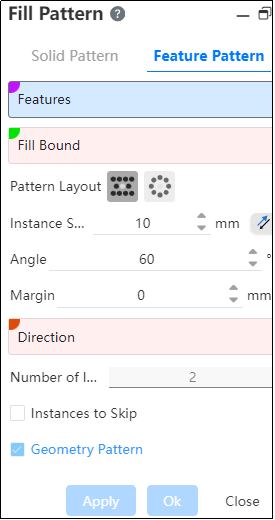
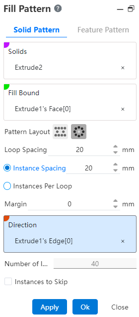
# Solid Pattern
1.Entity: Picks up the entity that needs the array operation.
2.Fill Boundary: Picks up a closed area as the array boundary.
Note:
The boundary is a closed plane sketch, a flat solid surface or a curved surface, and the plane where the fill boundary is located needs to intersect or coincide with the entity.
3.Array layout: Used to set the distribution style of array instances, there are two options, namely "perforation" and "circumference".
- Perforation: A layout method often used for sheet metal perforation, through the location of the source to make some auxiliary lines with a certain Angle to the selected direction, instances are distributed at the intersection of these lines.

- Instance spacing: set the distance between the center of the instance;
- Angle: Set the Angle of the array instance to the selected direction;
- Margin: the distance of the contracted boundary range offset inward;
- Direction: This direction is paired with the Angle as the arrangement direction of the array.
Note:
Can pick up sketch line, two points, solid edge line or reference line as the direction basis.
Instance number: Displays the number of instances (including the source) generated within the boundary under the current setting parameters in real time, which is only displayed and cannot be modified.
Circumference: Multiple circles are extended outward with the source as the center, and instances are distributed on the circular edges.

Ring spacing: Sets the "offset" distance between the circles;
Instance spacing: Choose between this item and "instances per loop", enter the number of instances on each circle;
Margin: the same "punch" margin;
Direction: Set array direction reference;
Note:
After selecting the direction, the point that intersects each circle along the direction from the location of the source is taken as the location of the first instance on each circle.
- Instance number: Displays the number of instances (including sources)generated within the boundary under the current setting parameter in real time, only for display and cannot be modified.
Number of instances = number of arrays * Number of instances per ring.
4.Skip Instances: After checking, select the model you want to skip in the array preview without generating the model.
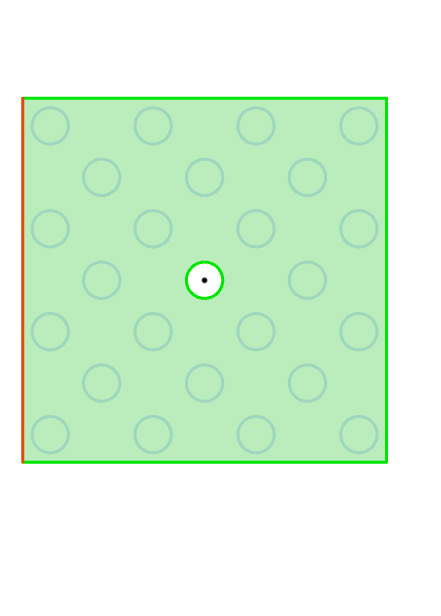
Example: Array layout select "Perforation", after setting the parameters, the physical array effect is as shown in the following figure.
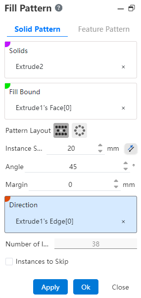
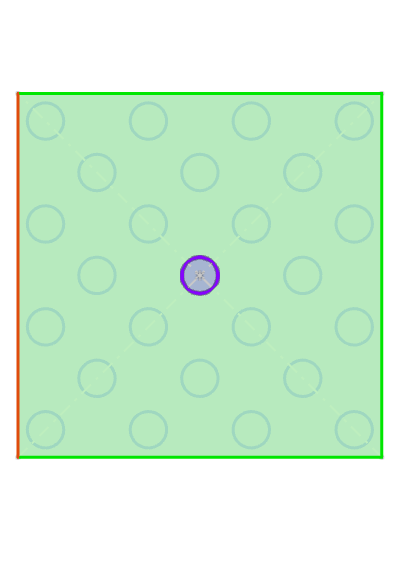
Example: Array layout select "Circumference", after setting parameters, the entity array effect is as shown in the following figure.
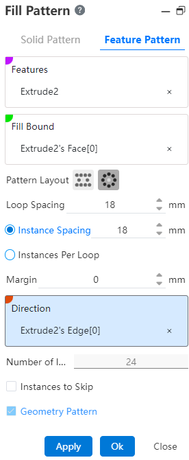
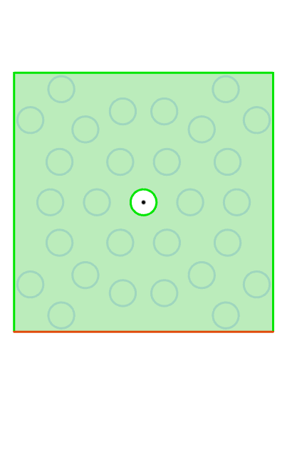
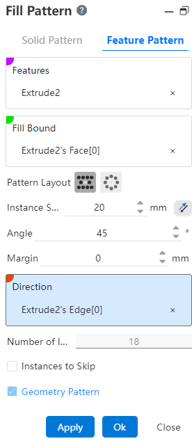
# Feature Pattern
1.Feature: Pick up the entity that needs the array operation.Support selecting already arrayed features as source features for further arraying.
2.Fill Boundary: Picks up a closed area as an array boundary.
Note:
The boundary is a closed plane sketch, a flat solid surface or a curved surface, and the plane where the fill boundary is located needs to intersect or coincide with the entity.
3.Array layout: Used to set the distribution style of array instances, there are two options, namely "perforation" and "circumference"
Perforation: A layout method often used for sheet metal perforation, through the location of the source to make some auxiliary lines with a certain Angle to the selected direction, instances are distributed at the intersection of these lines.
- Instance spacing: set the distance between the center of the instance;
- Angle: Set the Angle of the array instance to the selected direction;
- Margin: the distance of the contracted boundary range offset inward;
- Direction: This direction is paired with the Angle as the arrangement direction of the array.
Note:
Can pick up sketch line, two points, solid edge line or reference reference line as the direction basis.
- Instance number: Displays the number of instances (including the source) generated within the boundary under the current setting parameters in real time, which is only displayed and cannot be modified.
Circumference: Multiple circles are extended outward with the source as the center, and instances are distributed on the circular edges.
- Ring spacing: Sets the "offset" distance between the circles;
- Instance spacing: Choose between this and "instances per loop", enter the number of instances on each circle;
- Margin: the same "punch" margin;
- Direction: Set array direction reference;
Note:
After selecting the direction, the point that intersects each circle along the direction from the location of the source is taken as the location of the first instance on each circle.
- Instance number: Displays the number of instances (including sources)generated within the boundary under the current setting parameter in real time, only for display and cannot be modified. Number of instances = number of arrays * Number of instances per ring.
4.Skip Instances: After checking, select the model you want to skip in the array preview without generating the model.
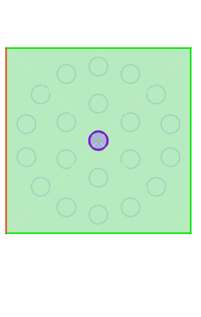
Example: Array layout select "Perforation", after setting parameters, the feature array effect is shown in the following figure.
Example: Array layout select "Circumference", after setting parameters, the feature array effect is as shown in the figure below.