# Hole Wizard
Used to create different types of holes using custom standards.
Click the toolbar  to open the Hole Command dialog box, whose command interface is shown in the following figure.
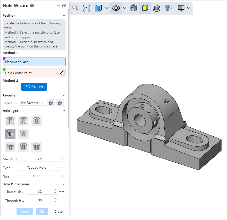
# Control Description
- Location:
Method 1: Select Drilling Surface and Bore Center Points
Drilling Surface: The face of the solid where the hole will be drilled.
Bore Center Point: The center of the hole, supports multiple selections.
【Points can be the origin, sketch points, solid vertices, circle centers, or points on a face.】
【Click the pencil icon behind the selection box to enter the sketch for bore center points.】
【After selecting the drilling surface, left-click directly on the face to pick a face point. In the dialog box, expand the face point to modify its UV parameters, adjusting the position of the point on the face.】
Note: When specifying the bore center point, hover the mouse over the circular edge until the center is displayed, then pick it as the bore center point.
Method 2: 3D Sketch
How to use:
Click the 3D sketch button to automatically enter the 3D sketch and start the point drawing command.
Click directly on the face to capture it and display the hole preview.
Exit the sketch, click "OK" to complete the hole creation.
Favorites:Select an existing saved favorite from the dropdown menu. Use buttons to add new favorites or delete existing ones.
Hole Types:8 types available: "Straight Hole", "Countersunk Hole", "Counterbored Hole", "Threaded Hole", "Tapered Threaded Hole", "Countersunk Slot", "Counterbored Slot", and "Straight Slot".
Standards:Supports custom, GB,ISO,DIN,JIS, and ANSI Inch (imperial) ,ANSI Metric thread hole specifications.
Type:Available when selecting " Non-custom" standard. Varies based on the selected hole type.
Specification:Available when selecting " Non-custom" standard. Choose the hole size from the standard.
Hole Dimensions:
Custom Standard: Users can define all hole dimensions.
Non-custom Standard: Dimensions are set based on the selected hole type, category, and size. Some dimensions are explicitly defined in Non-custom standards. Click "Restore Defaults" to revert custom dimensions to Non-custom standard values.
Termination Methods:There are various extending methods available, including "given depth," "through all," "to a specified distance from a selected face," "form to face," and "form to next face."
Termination Depth:Set the depth value when "Given Depth" is selected as the termination method.
Top Cone Angle:Set the end angle and angle value when "Given Depth" is selected as the termination method.
Thread Depth:Set the termination method and depth when the hole type is "Threaded Hole".
Equal to Termination Depth:When both termination depth and thread depth are set to "Given Depth", this option allows setting both values to be equal.
Options:
Screw Clearance: Selecting this option increases the depth of the recessed area above the countersunk or counterbored hole. The added depth can be specified. For counterbored holes, the method of increasing depth can be selected.
Near End/Screw Under/Far End Taper: Selecting this option adds tapered features similar to chamfers at specified locations. The feature dimensions can be set using distance and angle.
- Feature Scope:Select the solid(s) to be drilled. The selection can be made automatically or manually specified.
# Hole
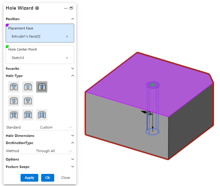
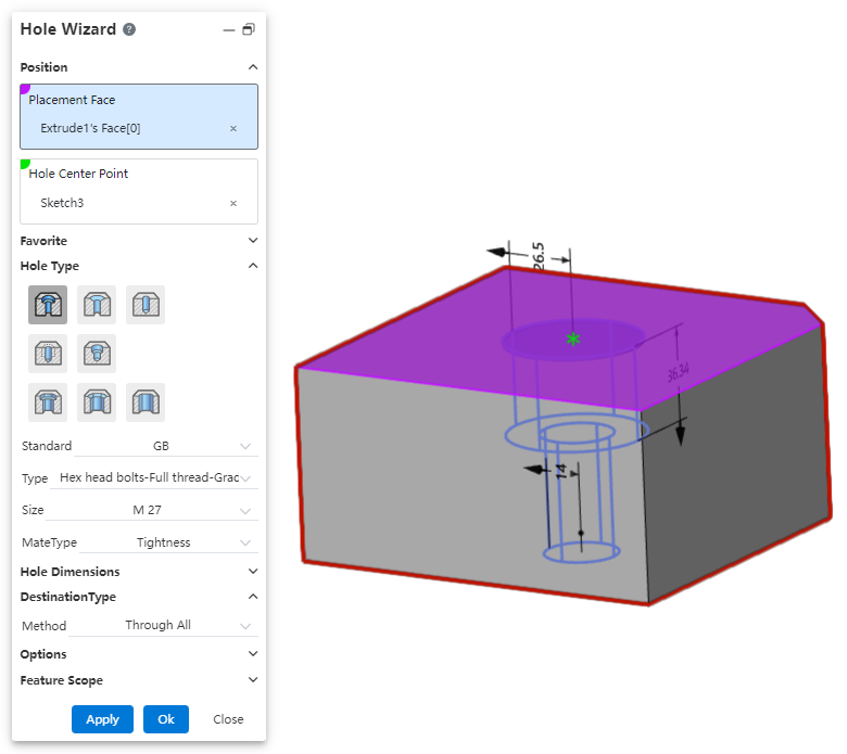
Example: select the straight hole style and select Through All for the extension mode, as shown in the following image.
# Counterbore
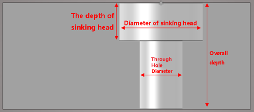
Through Hole Diameter: The diameter of the hole section.
Countersink depth: The depth of the countersink section.
Countersink diameter: The diameter of the hole in the countersink part.
Termination Method: There are a variety of termination methods.
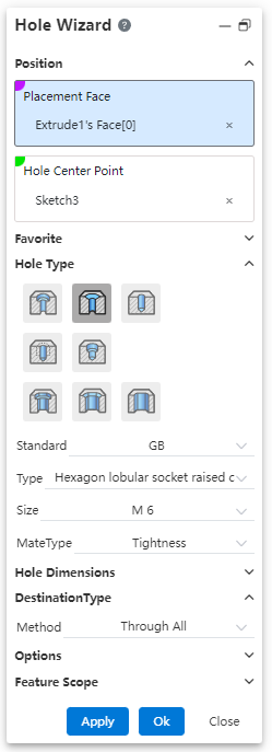
Example: Set the relevant parameters, countersunk hole preview effect as shown in the following figure.
# Countersink
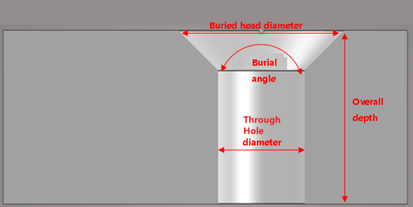
Through Hole Diameter: The diameter of the hole section.
Countersunk Angle: countersunk Angle.
Countersunk diameter: countersunk diameter.
Termination method: There are several termination methods, respectively, "through all", "given depth".
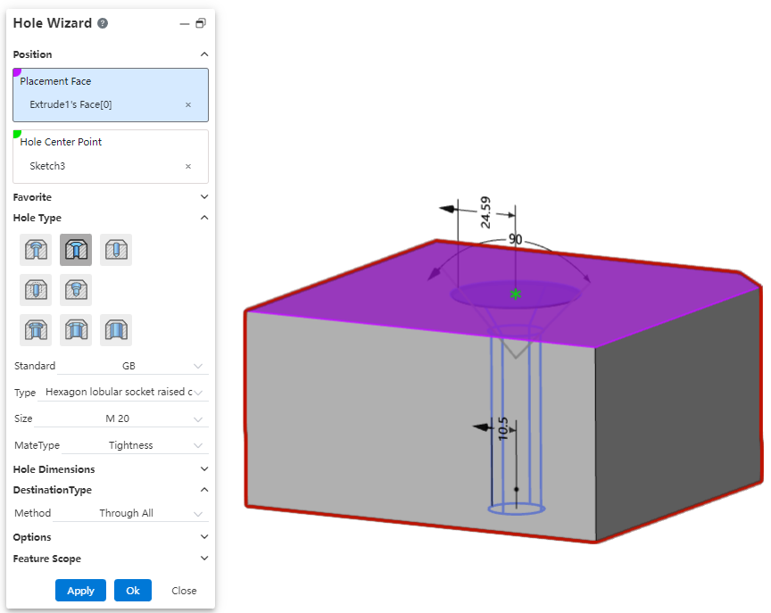
Example: After setting the relevant parameters, select "through all" as the extension method. The preview effect is shown in the image below.
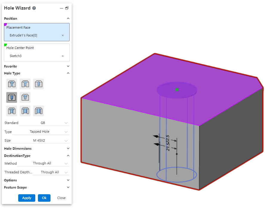
# Threaded Hole
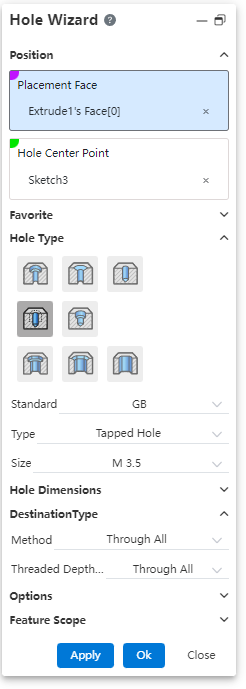
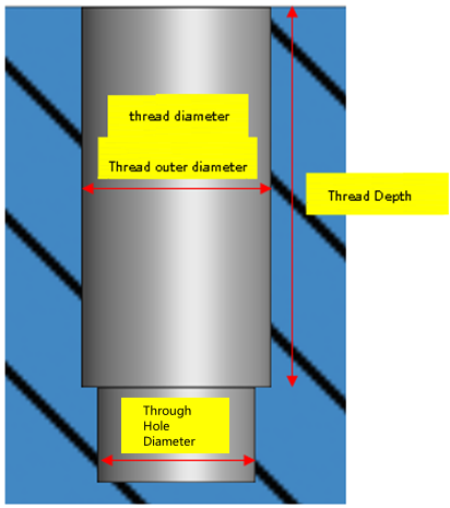
Through Hole Diameter: The diameter of the hole section.
Thread diameter: the outside diameter of the thread.
Thread depth: The depth of the hole thread, which supports customization.
Termination depth: the overall depth of the hole, which supports customization.
Termination Method: There are several termination methods.
Display way: There are three display ways, respectively, "cut the thread", "ignore the thread", "decorative thread". When using the Cut thread option, you can choose to display the decorative thread line.
Automatically calculate the depth:Usually, there is a correlation between the depth of the thread and the overall depth of the hole, and the system supports automatically calculating one depth based on the other depth.
- When the "Automatic depth calculation" button
 behind the depth is pressed, it means that the depth will be automatically adjusted according to the other depth.
 - You can manually click the "Automatically calculate Depth" button as required to switch its pressed state to control whether the system needs to automatically calculate this depth.
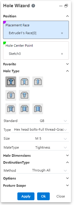
Example: Set the relevant parameters, the threaded hole preview effect is shown in the following figure.
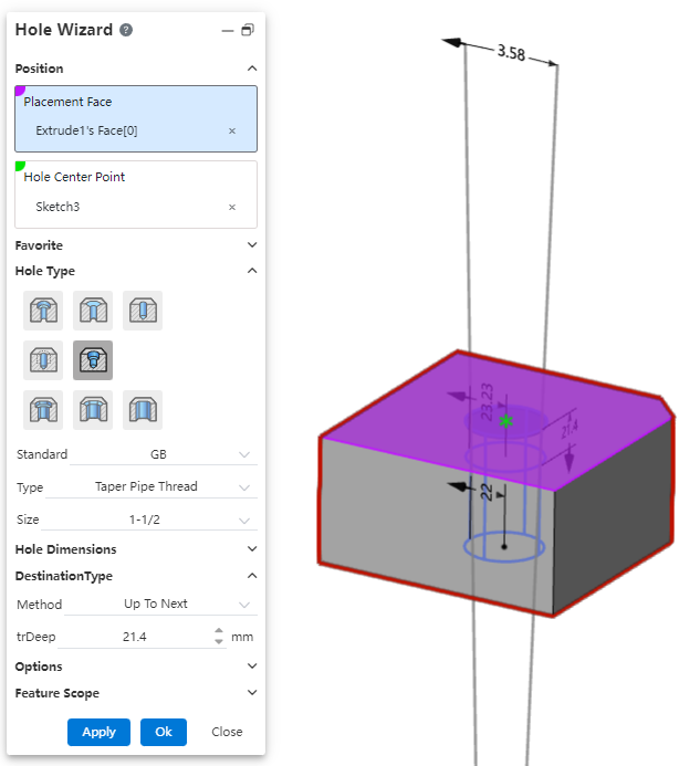
# Tapered Hole
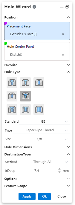
Diameter: Hole diameter.
Thread depth: The thread depth of the hole, which can be customized.
Termination depth: the overall depth of the hole, which supports customization.
Display method: There are three display methods, respectively, "cut thread", "Ignore thread", "decorative thread".
Automatic calculation of depth:Usually, the depth of the thread and the overall depth of the hole there is a correlation, the system supports the automatic calculation of another depth according to one depth.
- When the "Automatic depth calculation" button behind the depth is pressed, it means that the depth will be automatically adjusted according to the other depth.
- You can manually click the "Automatically calculate Depth" button as required to switch its pressed state to control whether the system needs to automatically calculate this depth.
Example: Set the relevant parameters, the threaded hole preview effect is shown in the following figure.
# Slot
"Countersunk hole notch, countersunk hole notch, straight hole notch" can be created.
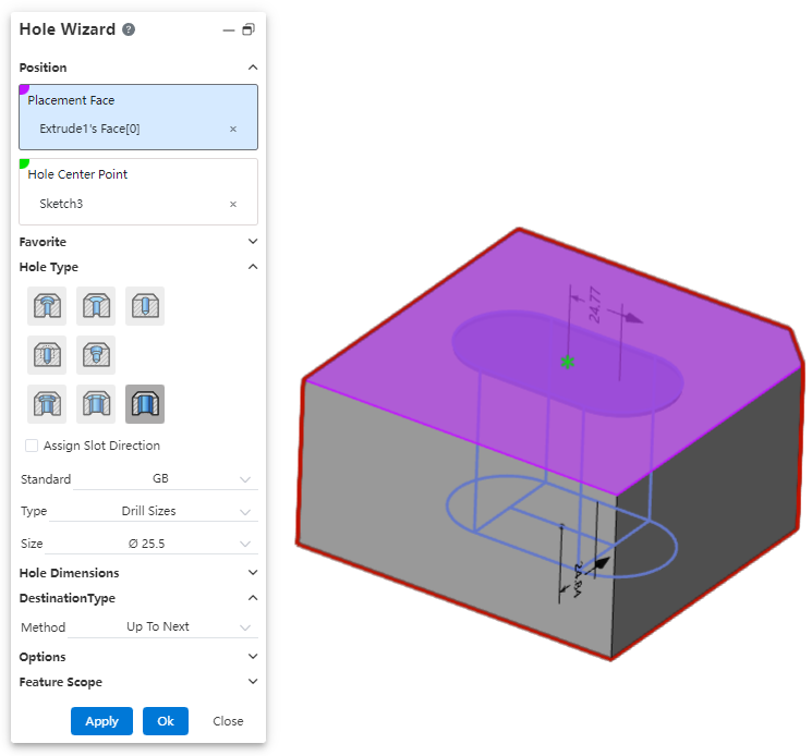
Dialog box control description:
Specify notch direction: The notch direction is aligned with the document absolute coordinate system by default, you can check this to specify other notch directions.
Hole type: You can select the "countersunk hole notch, countersunk hole notch, straight hole notch" type.
Notch length: Set the notch length, which can be selected by the size scheme as shown in the range of the length.
Groove Angle: Make the groove in the default direction based on the rotation of the set Angle, you can click the button behind the reverse rotation.
Other parameters: consistent with the corresponding round hole parameters, such as "countersunk hole notch" and "countersunk hole" parameters.
# Custom Hole Styles
You can bookmark custom hole parameters so that they can be called repeatedly in subsequent designs.
To create a favorite:
1) Open the parts document and click on the [hole] command.
2) Select the desired type of hole and customize the modification parameters as needed.
3)Click the "Add or Update Favorites" button  .
.
4) Enter a name for your collection.
5) Click OK and the creation is complete.
To use Favorites:
1) Open the parts document and click on the [hole] command.
2) Set the appropriate punch face and hole center point.
3) Select the desired type of hole.
4) Select the collection you want to use.
5) Click OK to create the hole feature using the parameters of the selected collection.
To edit the collection:
1) Open the parts document and click on the [hole] command.
2) Select the type of hole you want to edit and modify the parameters as required.
3) Click the "Add or Update Favorites" button .
4) Select the name of the hole collection you want to edit from the drop down box, and the dialog box will prompt "Will update this collection."
5) Click OK, the editing is complete, and the selected hole collection is updated to the new parameters set in step 2.
Note:Editing the favorites does not affect the hole features that have already been created.
To delete a collection:
1) Open the parts document and click on the [hole] command.
2) Select the hole collection you want to remove.
3) Click the Delete Favorites button  .
.
4) Select the name of the hole collection you want to edit from the drop down box, and the dialog box will prompt "Will update this collection."
5) Click OK, the editing is complete, and the selected hole collection is updated to the new parameters set in step 2.
Note 1:Deleting a collection does not affect the hole features that have already been created.
Note 2:Hole favorites can also be deleted in system Settings, see "Managing Favorites" for details.
To Manage your favorites:
1) Open the "System Settings - Template Management - Hole Favorites" page.
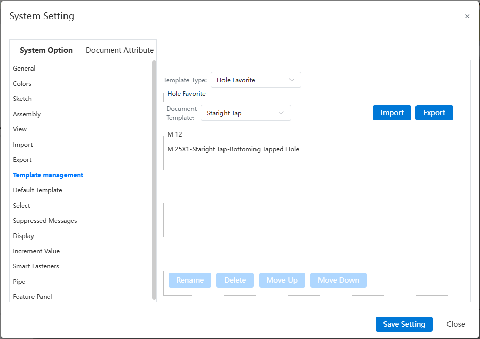
2) Select the type of hole and the specific hole collection you want to manage.
3) You can perform management operations such as Delete and rename by clicking buttons on the interface.
Import/Export Favorites:
1) Open the "System Settings - Template Management - Hole Favorites" page.
2) Click the "Export" button, and the hole favorites data file can be downloaded to the local PC through the browser.
3) Click Import, select an existing local data file, and set how to handle the Duplicate hole data file.
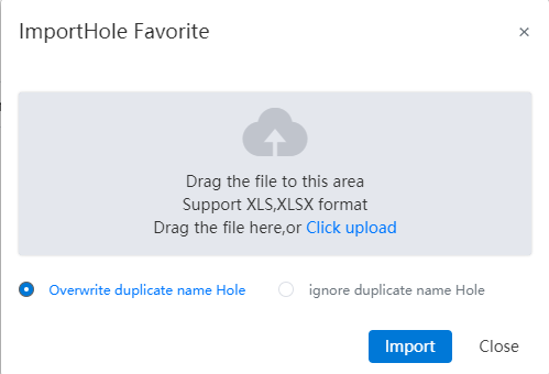
4) Click the "Import" button to complete the import.
Note:Import and export operations affect all types of hole collections.
# Termination Condition
Through all: The hole runs completely through the entity in the specified direction.
Given depth: When generating the top cone Angle, you can set whether the depth includes the top cone Angle at the bottom of the hole.

Shape to face: Refer to the stretch cut method, select a face where the hole terminates.
Support plane/surface, optional datum or solid surface of the surface.
Optionally tangent to or across the selected surface.
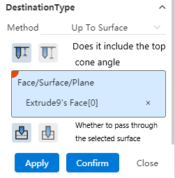
Take tangential as an example: If you choose to include the top cone Angle, then the tip of the hole is tangent to the face; If the top cone Angle is not included, then the shoulder line of the hole is tangent to the face.
To the specified distance from the specified face: Select a face and set the forming distance to this face.
Optionally specify the distance from "shoulder line, top" to this face.
You can enter a range [-0.1, 1e7], where a negative number indicates passing through the selected surface, and an integer indicates not passing through the selected surface to maintain a certain distance from the selected surface.
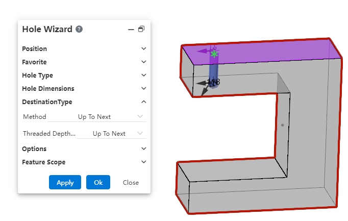
Up to next:When this option is selected, there's no need to manually calculate the hole depth—the hole will automatically terminate at the next face.
# Multi-Body Drilling
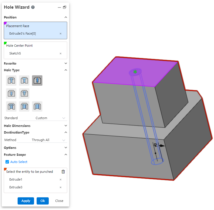
How to use:
Open the "Hole Wizard" command.
Set the hole's style, parameters, position, etc.
In the "Feature Scope" options, select the solids to be used for drilling.
Click OK to generate the holes.