# Transform
Lets you adjust the position and orientation of components.
Click the toolbar to open the Transform Command dialog box, whose command interface is shown in the following figure. .
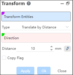
Transform object: can be entity, surface, grid.
Transformation Method: There are five methods, namely "translation by distance", "rotation", "translation by XYZ, coordinate system", "point to point". Different transformation methods correspond to different parameters, and there are different preview effects.
Copy: Check by default to copy the transformed object and transform the copy; Uncheck to move the transformed object.
Note:Multiple selected geometers, each of which is transformed separately, rather than all of which are combined into one whole.
# Translate by Distance
Transform objects are translated at a specified distance.
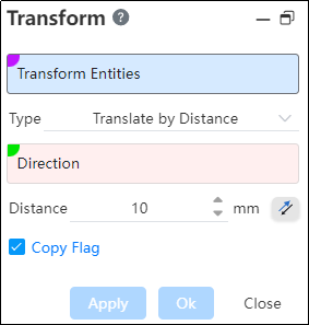
Example: Use a hexagonal entity as a transform object by selecting Pan By Distance with its edges in the direction, as shown in the following illustration.
# Revolve
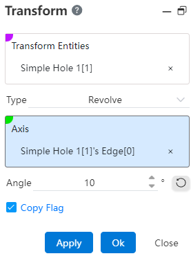
Transform objects rotate according to the axis of rotation. The functions of each control are as follows:
- Axis: It is used to locate the direction of the rotation axis. The rotation axis will be parallel to the selected reference axis and over the center of gravity of the transformed object, and the transformed object will rotate around this rotation axis.
Note:
The axis can be a sketch line, a solid edge, or two points.
Angle: Rotation angle.
Copy: Check by default to copy the transformed object and transform the copy; Uncheck to move the transformed object.
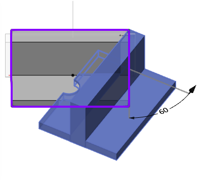
Example: Rotate mode, with the solid edge as the axis of rotation, check Copy, and the preview effect is shown in the following figure.
# Translate along XYZ
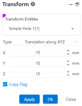
The transform object is translated in the X, Y, and Z coordinates.
X: The translational distance in the X direction.
Y: The translational distance in the Y direction.
Z: Translational distance in the Z direction.
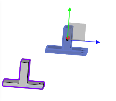
Example: Under XYZ translation mode, modify the translation distance, check Copy, and the preview effect is shown in the following figure.
# Coordinate System
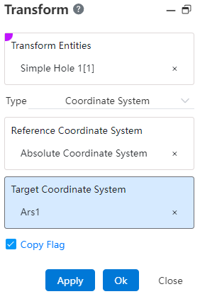
The transform object moves according to the reference coordinate system and the target coordinate system.
Reference coordinate system: Select a single, viewport click to select a coordinate system for solid points/sketch points as the reference coordinate system.
Target coordinate system: Single click through the feature panel or viewport to select a coordinate system as the target location.
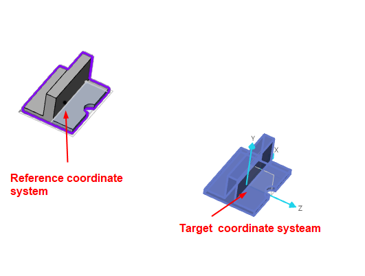
After the selection is completed, the distance to be moved from the reference coordinate system to the target coordinate system and the Angle of rotation are automatically calculated, the element is moved and rotated the same, and the position transformation is completed or a copy is generated.
Example: Under the coordinate system mode, check the copy, the preview effect is as shown in the following picture:
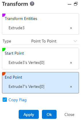
# Point To Point
An object is transformed by moving from a starting reference point to another target reference point.
- Starting Point: Click to select a point via the Feature Panel or Viewport as the starting point.
- The Feature Panel supports only selecting reference points, while the Viewport supports selecting reference points, entity points, and sketch points.
- Target Point: Click to select a point via the Feature Panel or Viewport as the target point.
- The target point cannot be the same as the starting point.
Once selected, the target element moves from the starting point to the target point.
Copy: Same as above.
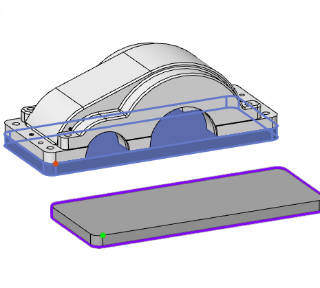
Example:In point-to-point mode, without selecting "Copy," the preview effect is shown in Figure:
← Mirror Linear Pattern →
