# Weld Frame
Click  on the "Frame" command to open the Structure member dialog box.The functions and application scenarios of each part are as follows:
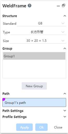
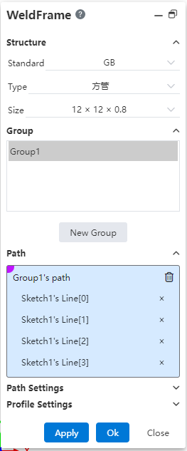
- Structural member: used to select the profile of the weldment.
- Standard: Standard for selecting the profile of the weldment in the drop down box. "GB, ISO、ANSI、ANSI Inch、DIN、JIS" is supported.
- Type: Select the type of outline included in the selected standard in the drop down box. Such as "C-slot, square tube", etc.
- Size: Select the specific specifications of the selected contour type in the drop down box. Such as "20x20x2, 20x40x2"
- Use Contour Material: When this is checked, the resulting entity is set to contour material
- Grouping: Used to create and select path groups.
- 1 group is automatically created when the command starts - "Group 1"
- Click on the command "New Group" to create a new group, named "Group 2.3..."
- Click to select a group. The group that is selected has a highlighted background color to indicate that it is currently selected.
- "Group 1" is selected by default when the command starts
- The new group is automatically selected after it is created
- Manually click on any group to select it
- The content displayed in "Path, Path Settings, Outline Settings" is the content of the currently selected group, so one group must be selected, no more than one group can be selected, and no group can be selected.
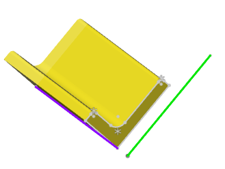
- Path: Select the path that belongs to the current group.
- Click on a sketch in the viewport to pick up a line segment, not the entire sketch
- Click on the x after the sketch line that has been picked up to delete the sketch line

- Component path selection requirements:
| Type | Requirements |
| Paths within the group | Choose non-guides in the sketch, not the whole sketch |
| Optional lines, arcs | |
| Spline curves are not optional | |
| A maximum of 2 lines are connected to the endpoints in the path | |
| Paths cannot be self-intersecting | |
| Lines from multiple sketches can be selected at the same time | |
| Supports picking parallel paths or connected paths | |
| Different group paths | Can be disconnected, can intersect |
| When intersecting, the member of the previous group cuts the member of the later group | |
| Can not be overlapped |
- Path setting: Set the weldment corners, welds, merges, etc.
Each setting takes effect only for the current group. The values of each setting should be saved in groups.
Apply corner treatment: Set the corner style at the connection of the component.
- Unchecked: Do not crop/extend the joints;
- Checked: When checked, two rows of buttons appear:
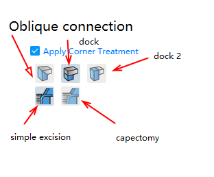
- "Miter, Butt 1, Butt 2" is the main option, you must select any one;
- "Simple Cut, Capping Cut" is a suboption of "Butt 1, 2", which is not displayed when the "miter" type is selected, and one must be selected when "Butt 1" or "Butt 2" is selected.
- By default, "Apply corner treatment" is checked and the "miter" mode is selected;
- The effects of each method are as follows:
Options Legend Untick 
Check - miter mode 
Check - Butt 1- Simple cut 
Check - Butt 1- Cap Cut 
Check - Butt 2- Simple Cut 
Check - Butt 2- Cap Cut 
In-group welds: Set the gaps between the internal members of the current group.

- Inter-group welds: Sets the value of the gap between the current group and other group members.
- Contour setting: Set the contour Angle, alignment, penetration point, etc.
Mirror contour: Set the contour mirror
 To mirror the outline sketch X axis and Y axis, respectively.
- Keep the penetration point position unchanged after mirroring.
- Neither is highlighted by default.
Not mirrored X-axis mirroring Y-axis mirroring 


Contour Angle: Set the contour rotation Angle.
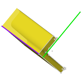
Align element: Select the align element and the outline automatically rotates and aligns with the selected element.
Select the orientation element in the viewport so that the sketch X-axis of the outline aligns with the projection direction of the selected element in the sketch plane.
Click
 the button after the aligned element to switch to the selected element aligned with the Y-axis and the button highlighted;Click again to switch back aligned with the X-axis and unhighlight the button.
Only elements outside the outline sketch can be picked up, not elements within the outline sketch itself. The optional element types are the same as the optional types for stretching the boss "direction".
When the alignment elements are not picked up, the sketch X-axis is aligned by default with the projection of the document absolute coordinate X-axis on the sketch plane. When the absolute coordinate X-axis has no projection direction on the sketch plane, it is aligned with the absolute coordinate Y-axis.
Alignment element not selected Align the X-axis Align the Y-axis 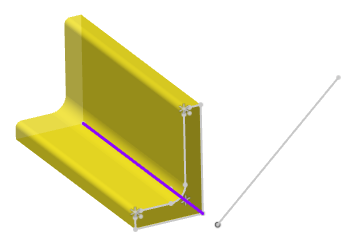
The rotation Angle can still be set after selecting the alignment element, so that the alignment direction is the rotation Angle set by rotating clockwise in the initial direction.
Penetration point: Customize the path with the penetration point of the outline.
- Pick up a point on the outline sketch and use it as the penetration point, optionally draw the point, end point and midpoint of the sketch reference and non-reference line.
- Only elements in the outline sketch can be picked up as penetration points, external elements cannot be picked up.
- When this item is not set, the default penetration point is the contour sketch origin.
- Click
 the button to display the outline sketch adaptively in the viewport. This button is used as an aid to facilitate the user to find the outline sketch to pick up the penetration point.
- The model preview updates instantly based on the selected outline, path, and Settings. The components of the currently selected group are highlighted and displayed separately from those of other groups.

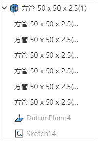
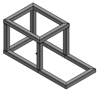
- After completing the required setup, click OK to generate the weldment model and a "structural member" feature.
← Cut Vent Trim/Extend →