# Trim/Extend
Trim the corners of the existing member into the desired style.
Click  the Cut/Extend command in the weldment module to open the Cut/Extend dialog box. You can choose "cut, miter, butt 1, butt 2" four ways to do the corner treatment.
- Clipping: Select the weldment entity as the entity to be clipped and a face or entity as the border. When selecting the face as the border, split the weldment entity and choose which parts to discard or keep; When selecting the entity as the boundary, extend or cut the weldment entity to the boundary entity.
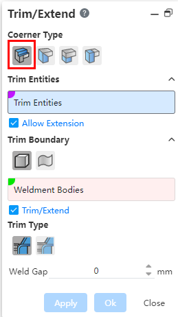
The corner type is selected to cut, and the specific parameter Settings and operations are as follows:
- Clipping Entity: Sets the entity to be clipped.
- Pick up frame 1: can only pick up the weldment entity, can choose more;
- 【Allow extension】:selected by default. When checked, the weldment entity can be extended to the border; If it is not checked, it can only be cut and not extended.
- 【Crop border】:Set the crop border.
- Pick frame 2: you can pick up "weldment solid" or "face (solid surface, surface, datum)", and switch the element to be picked up by "Select body, select face" button.
- 【Clipping/Extension】:This item is displayed only when it is set to "select body", and is checked by default. When checked, the scope of the selected boundary entity can be extended; If it is not checked, the scope of action of the selected boundary entity cannot be extended.
- 【Clipping mode】:This item is displayed only when it is set to Select Body. Optional "Simple cropping
 , capping cropping
 ", the default is simple cropping.The simple crop end face is flat, and the capped crop end face coincides with the border.
 - 【Weld gap】:Set the distance between the weldment entity to be cut and the end face of the boundary entity.
- Miter: Select two weldment entities and cut/extend the selected weldment entity to miter it.
- 【Cut entity】:Select the weldment entity to be cut.
- 【Cut border】:Set the cut border entity.
【Crop reference point】:Non-required, can be filled at the viewport pick point to pick box 3.
- Optional point types: model vertex, midpoint, sketch line endpoint, midpoint, reference point, sketch drawing point.

- The crop surface is located in the middle of the two entities by default.
- If the clipping reference point is picked, the clipping surface is offset through the selected point.
【Cutting method】:Support two methods "full flat head miter
 ", "equal Angle miter
 ", the default is "full flat head miter".As shown in the following figure, when the size of the component outline of the selected component is different, the result of selecting different cutting methods is different.
【Weld gap】:Set the distance between the weldment entity to be cut and the end face of the boundary entity.
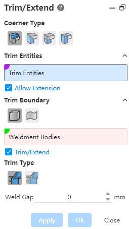
Butt joint: Select two weldment entities and cut/extend the selected weldment entity to butt it.
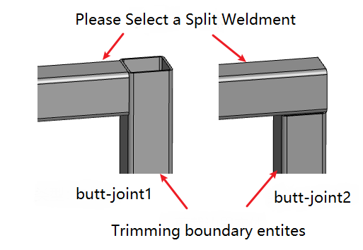
- Butt 1 and butt 2 effect pairs such as the one above
- 【Clipping entity】:Set the solder body to be clipped.
- 【Cut border】:Set the cut border entity, only the weldment entity can be selected.
- 【Cutting method】:This item is displayed only when set to "select body". Optional "Simple cropping, capping cropping", the default is simple cropping.The simple crop end face is flat, and the capped crop end face coincides with the border.
- 【Welded gap】:The default is 0, and the input range is ≥0. Used to set the distance between the weldment entity to be cut and the end face of the boundary entity.
- 【Cutting method】:This item is displayed only when set to "select body". Optional "Simple cropping
- Update viewport preview in real time according to dialog box setting item.
- When the selected element cannot be cropped, an error should be reported, prompting the user "Selected element cannot be cropped".
← Weld Frame Gusset →