# Weld Bead
Generate lightening elements (similar to decorative thread lines) representing the weld path and corresponding weld symbols by selecting the weld path.
Application scenarios:
- Click the 【Weld】
 command in the weldment module to open the "Weld" dialog box.
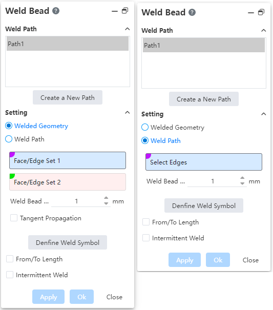
Weld Path: Used to create and select a weld path.
Set: Used to select the welding path and set the radius of the weld.
Welding path picking method: in the "welding geometry, welding path" choose one of the two, the default is "welding geometry" method.
【Welding Geometry】:When selecting this method, two pickup boxes are displayed "face group or edge group 1, face group or edge group 2"
- Face group refers to the selection of multiple faces on the entity, combined into a face; Line group refers to selecting multiple solid side lines and combining them into one line.
- Only solid surfaces or solid edges can be picked up, surfaces or other type elements are not supported.
- Faces/lines in the same group should belong to the same entity.
- Group 1 and group 2 support the combination form of "plane group + plane group, line group + line group, plane group + line group".
Face group + line group Line group + line Face group + line 


- The "face group + face group" form requires that the two sets of faces belong to different entities; Other combinations can belong to the same entity or different entities.
- Tangential extension: Only welded geometry mode is available. Automatically recognize tangent paths when checked.
- Select/Both sides/Full Circumference: Only weld geometry mode is available. Used to select the relevant edges while influencing the weld symbol style. Default to select.
| Select | Generate the weld only on the identified path, The weld symbol is shown on only one side |   |
| Both sides | Generate welds on the current and opposite paths, Display both numerical values and symbols on the welding symbol |   |
| The whole Circle | Generate welds along the entire path, Show the full circle symbol on the weld symbol |   |
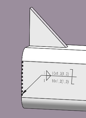
Note:For welds generated by welding geometry, the arrow points to the nearest element in Group 1 and is associated with that element.
- 【Welding path】:Select a continuous solid side line and create a weld at the side line.
- 【Weld radius】:Set the weld and the radius of the corresponding lightening element.
- 【Define welding symbol】:Click to open the MBD welding symbol setting window.
- "From/to" length: The starting position and length of the weld can be set.
- This is left unchecked by default, meaning that the weld coincides exactly with the selected path.
- When checked, you can set the starting point and length

- Intermittent welding: Set the weld in a "dashed line" shape.
Unchecked by default, welds are in continuous solid line shape.
After it is checked, the weld becomes a broken "dashed line" shape. You need to select either "Gap and weld length" or "Pitch and weld length" to set the specific parameters.
- "Gap and weld Length" : Set the weld length and gap length.
- "Pitch and Weld Length" : Set the weld length and pitch length

- Weld Length: The length of the welded part
- Gap length: The length of the gap that is not welded
- Pitch length: the total length of the pitch of each welded length + the length of the gap
After intermittent welding is checked, the total length of welding is not displayed on the welding symbol, but the related parameters of intermittent welding are displayed
Interleaving: This parameter is optional only when both sides is selected.

- Staggered welds appear on both sides.
- Interlaced symbols appear at the end of the weld symbols.