# End Cap
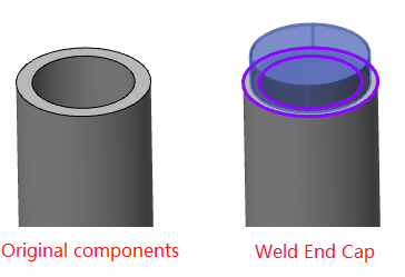
Used to create a top cap at the end of the tube type weldment. The top cap is a common entity.
Application scenarios:
- Click
 the 【Top cover】 command in the weldment module to open the "Top cover" dialog box.
【Face】:Pick up the end face of the tube type weldment entity and generate the top cover at the selected end face:
Tube type Tube tube type (multi-inside profile) Non-tube type 


- Support for multiple choices
- Only the end face of the tubular welded body can be selected, non-tubular welded body can not be selected, and ordinary solid surface can not be selected.
- The end face must be flat
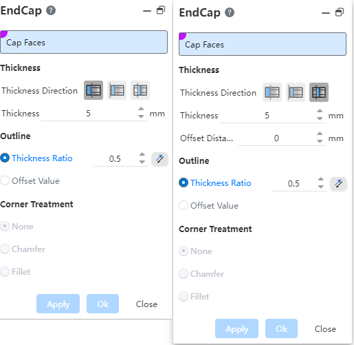
- Thickness: Used to set the thickness starting position and thickness value for the top cover
【Thickness direction】:Optional "outwards
 , inwards
 , inwards
 ", default is"outwards".
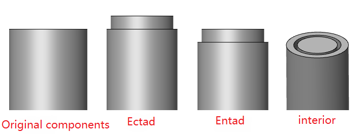
- Outward: thickening outward from the selected end face to generate the top cover, and the length of the original member remains unchanged.
- Inward: The top cover is thickened inward from the selected end face, and the original member is shortened to fit the top cover
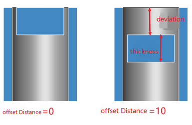
- Internal: The top cover is generated inside the member, and the 'offset' distance between the top cover and the selected end face can be set, and the length of the original member is unchanged.
- When the selected end face has multiple inner contours, "inside" can not be selected.
【Thickness】:Used to set the thickness of the top cover. The default value is 5, allowing the input range > 0.
【Offset】:Control the position offset parameter of the corner support plate
【Position】:When the support surface is "plane + plane", this setting item will be displayed, and you can choose "one side, centered, another side"
- Contour: Used to set the contour size of the top cover

- The outline of the top cover is related to the "thickness direction" and the solid structure outline of the weldment
- When the thickness direction is "outward and inward", the outline of the top cover is the same as the outer outline of the structure outline
- When the thickness direction is "inside", the top cover outline is the same as the inside outline of the structure outline.
- The top cover outline ignores the rounded corners in the structure outline
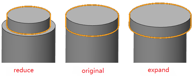
- You can choose either way in the "Thickness ratio, isometric value" to expand or shrink the outline, and display the input box and reverse button after the selected mode. The default is thickness ratio.
- 【Thickness ratio】:By entering the ratio, the top cover profile is shifted inward or outward by x, x= thickness ratio * structure profile thickness.
- 【Offset value】:By entering the offset value, when the top cover is offs et inward or outward the corresponding value
- Click the reverse button to make the switch shrink inward and expand the outline outward. The default is offset inward
- If the input value is too large and offset inward, the top cover may disappear or the contour will self-intersect. In this case, an error message "cannot generate the top cover, please check the offset value" should be reported.
- When "Thickness direction" is selected "Internal", the reverse button is not available, and the top cover can only be reduced inward.
- Corner treatment: Used to set the treatment of the top cover corner
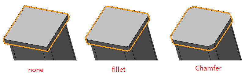
- You can choose any of the "None, chamfer, rounded" options, the default is "none"
- 【None】:The corner of the top cover is not processed
- 【Rounded】:Round the side edges of the top cover. When this method is selected, a numerical input box is displayed after the rounded corner option to set the radius.
- 【Chamfer】:Chamfer the side edges of the top cover with a symmetrical "distance/distance chamfer" type of chamfer.