# Modeling Interface
Modeling Interface Overview
It mainly includes all the components of CrownCAD: function command, feature tree, file management, view window and so on.

| Number | Instruction | Number | Instruction |
|---|---|---|---|
| 1 | Navigation Bar | 6 | Document List |
| 2 | System Management | 7 | Feature Management |
| 3 | Toolbar | 8 | Document Location |
| 4 | View Toolbar | 9 | Graphic Area |
| 5 | View Management | 10 | Feedback |
# Navigation Bar
In the CrownCAD navigation bar, you can do project Settings, new documents, import/export.
# ICONS
Click on the icon  anywhere to return to the project management page.
# Project Settings
Click on the project name to display the Settings screen for the project, as follows.

Project Type:Public, Private. Private items can only be viewed and modified by the current user, and Public items can be viewed or copied by other users.
Project Name:Modify the name of the project.
Archive Mode:Submit the document for the activity, you cannot edit the project after archiving.
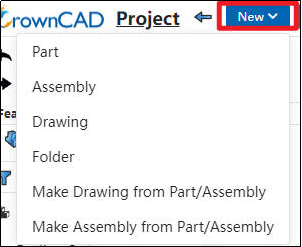
# New
Click the “New” option in the upper-left corner, and from the drop-down menu you can select: Part, Assembly, Drawing, Folder, Making Drawing from Part/Assembly, or Making Assembly from Part/Assembly.
# Import/Export
# Import/Export Intermediate Files
Can support common file formats, such as IGES, STEP, etc., specific instructions can see the data exchange related content.

# Import/Export CrownCAD Files
To import and export CrownCAD files, click “Export To Local Files” in “Import/Export” and Import CrownCAD File. You can determine whether to export the CrownCAD file including engineering drawings, standard parts, and templates. The exported files can be imported to the CrownCAD file.

How to use:
Export to local:
Select [Export To Local Local] from the Import/Export drop-down box.
Set the check box to control the special content to be included when exporting, including drawings/standard parts and templates.
Select Nested View/Flat View to set whether to indent the files in the file list according to their affiliations.
File list, check what you want to pack.
Number of documents: Displays the number and total number of selected documents for each category to be packaged.
Document structure: Select the exported document structure.
Compressed package name: Enter the compressed package name, which defaults to the project name.
Click Export, select the template to be exported, support the user manual search or the system automatically search according to the selected document.
Click OK.

Import the CrownCAD file:
Import, click the Import/Export drop down box and select Import CrownCAD file.
Package the model file along with the referenced template file.
Confirm the import, the system automatically recognizes and uses the template file.
Instructions:
When exporting the template file, the template file and model file are packaged as a zip compression package.
You can upload the template file as an unpacked file or as a ZIP package, but you cannot upload the template file together.
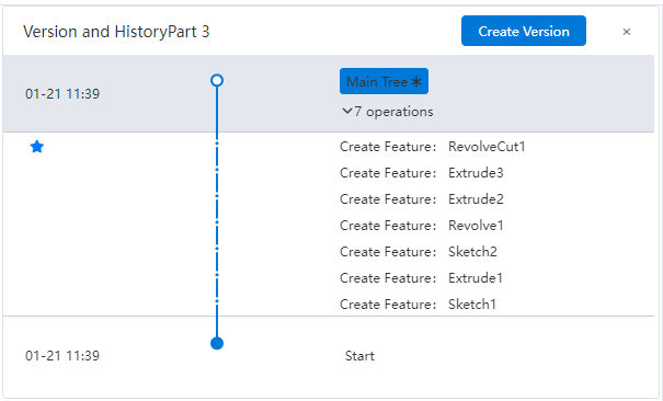
# Version Management
Click  to manage the branches and nodes of the current document. See Versioning.
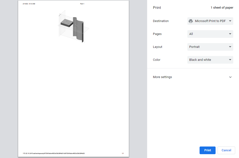
Click  , Parts and Assembly to print the current viewport image.Engineering drawings preferentially print the selected drawing content.
# Save
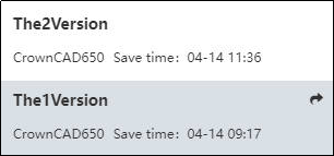
Click  , you can save the current operation history, save location will appear "save time"
  or "successfully saved"
 .At the same time, in the version management, you can see a blue five-pointed star mark in front of the time node.
- Click Save, the right side of the viewport can open the save record, you can view all the saved records.

- Click the rollback
 after a time node record to open the rollback dialog box. After confirming it, it will directly jump back to the model status of the time node, and the navigation bar will update the latest save time.
# Pack And Go
Using the 【Pack And Go】 feature allows you to efficiently collect and copy Parts, Assemblies, Drawings, and associated documentation.
How to use:
Click on the Packing command in the Save drop-down menu.
Within the dialog box, set the content to be packed, including whether to include Drawings or Standard Components.
Browse and select a new location if you wish to change where the packed files will be saved.
Check “Add Prefix” or “Add Suffix” as needed.Enter your desired text in the provided fields. Each new name will then include the specified prefix/suffix.
Click Save to finish the packing process.
# Save as Document
Use the 【Save As Document】 feature to create a new version or copy of your currently open document.
How to use:
With the document open, click on "Save as Document" in the dropdown menu of the save icon.
In the "Save As" dialog box, specify the name of the new document to be created.
Set the location where the new document will be saved.
Configure whether to include all referenced documents:Check the option to copy both the current document and its referenced documents.Uncheck to only copy the current document.This feature is available for assembly and engineering drawing documents.
Config whether to "Save as And Open":Check the option to open the new document after saving.Uncheck to only save without opening the new document
Click "Confirm" to complete the save operation.
# Save as Template
Click  Save as Template in the drop down box to save the current document and its property Settings as a template.
# System Tools
System tools include the following aspects:

# Multi-window
With the multi-window function, when multiple documents are opened, multiple documents can be displayed tiled under one window and can be operated normally.

How to use:
After selecting any document to open, click [Window Layout] button in the navigation bar.
Click the drop down button and select the tile effect [Tile Horizontally] or [Tile Vertically].
Instructions:
- No more than 32 documents can be opened.
After refreshing the web page, keep only the last activated documents.
# Command Search
The command search function quickly finds commands. Click the button ; Enter the name of the command you want to look for in the Search command window
  to quickly find the command. You can either tap the name directly to launch the command, or tap to locate the command.

# Like
Click  to like the current document and to see the number of likes.
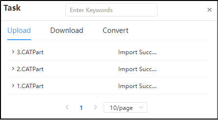
# Task
Tasks  are used to record upload, download, file conversion progress and other processes, and its interface is as shown in the following picture:
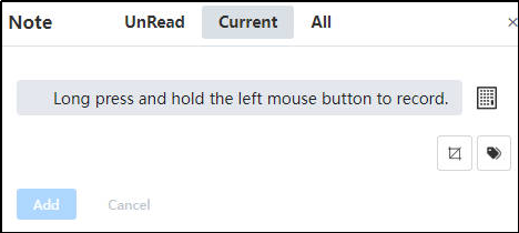
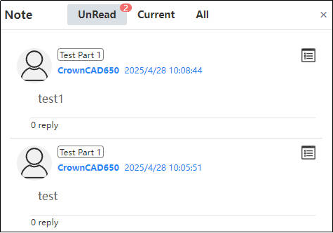
# Comments
Comments  can be shared with other users through links or user Settings. Comments and replies can be made here. The interface is as follows:
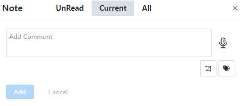
The control description is as follows:
- Current: The add comment dialog box is displayed without comments, and the add order is displayed from bottom to top when there are comments;
- All: Displays all comments;
- Voice
 : Click to switch between voice input and text input. After switching to voice input, hold down the left mouse button to record.
- Selecting Elements
 : you can pick up the graphic element of the viewport to add a mark;
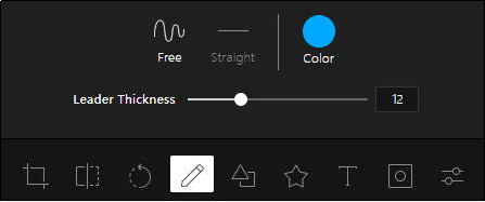
 - Screenshot
 :Capture the entire graphics area of the software, and can crop, mirror, rotate, comment, filter and other operations on the screenshot of the picture.
- When a message is received, the number of unread messages will be displayed in the upper right corner
 of the comment icon.Click on it to reply to the comment, click on the image to see a larger image, click on the white box next to the question comment, and check it to close the question.
# Share
Sharing  can be shared with other users, teams, and activities through links or user Settings, and set permissions (edit or read only), its interface is as follows:
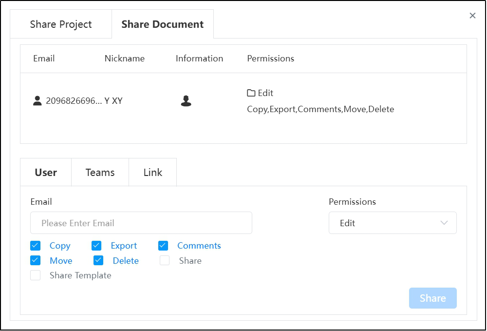
For specific functions, refer to Sharing collaboration.
# Setting
See Settings for System Settings.
# Help
Refer Help for details.
# Toggle Theme Style
Refer to Toggle Theme Style for details.
# User Settings
Refer to User Settings for details.
# Toolbar
The toolbar displays the available function ICONS, supports the display of ICONS or graphic display, mobile and other user-defined, can be set in the System Settings-Toolbar.

# View toolbar

# Zoom to Fit
Click  to display all unhidden elements in the current document in the viewport.Right click "Zoom to Fit".
# Open Zoom to Area
Click  and select an area in the viewport box to focus the viewport on the area selected in the box. Right click "Open Zoom to Area". To exit focus, click or right click "Close Zoom to Area".

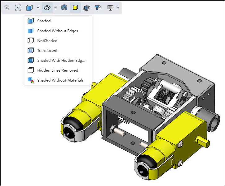
# Render Mode
Set the render style of the parts, the render style is shown as the following image, the default display is coloring.
# Display Toolbar
Unified management size, constraints, coordinate system, origin and other display state.

Control elements are shown in the following table:
| ICONS | Name | Remarks |
|---|---|---|
 | Sketch Constraint | Drafts and drawings take effect within, and are not subject to overall explicit and implicit control |
 | Dimensional Constraint | Only take effect within the sketch, not subject to overall explicit and implicit control |
 | Origin | |
 | Point | |
 | Axis | |
 | Plane | |
 | Coordinate System | |
 | Curve | |
 | Sketch | |
 | 3D Sketch | |
 | Document MBD | |
| Component MBD | Assembly only |
 | Annotation | |
 | Cosmetic Thread | |
 | Center of Mass | |
 | Connection Point |
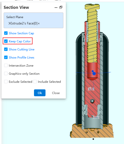
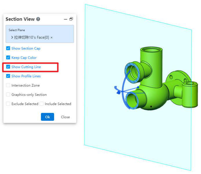
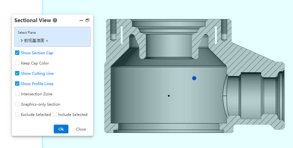
# Section View
Click  to open the cut command and display the cut view of the model.
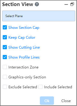
Description of each control:
- Select Plane: Select one or more solid planes, planes, datum planes.
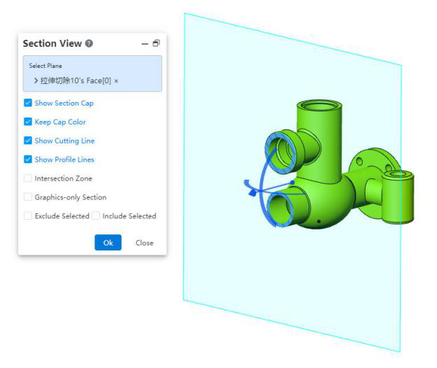
- Keep Cap Color: When creating section views in Part or Assembly, it supports displaying the component's original color on the section face.
- Show Cuting Line:The cut plane is shown as a cut line.
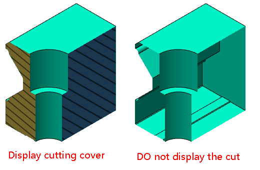
- Show Section Cap: Display the profile effect in a specified color. Leave this option unchecked to see inside the model.
- Show Profile Lines: Displays the edges of the model's cut plane after it is cut.

- Intersection Zone: The partitioned display is defined by the intersection points of the selected datum or plane and the boundary boxes of the model. When not selected, the plane of the profile view is displayed.

Exclude Selected: The selected entity will no longer be cut.
Included Selected: The selected entity will be sliced. No other entity will be cut. Click again
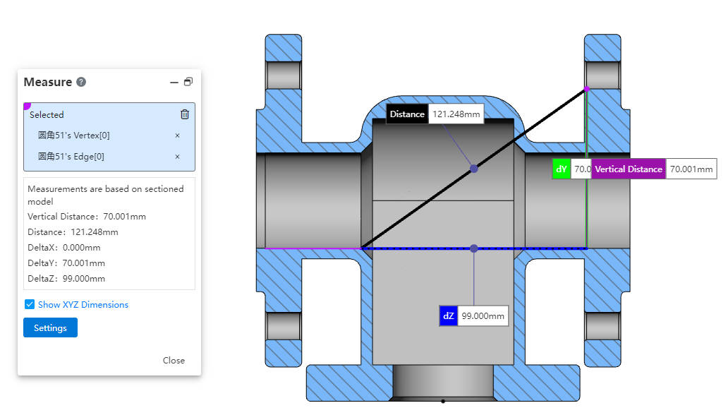
to exit the section view.Cutting measurement: Create a section view in parts and assemblies, and support the use of measurement commands to pick up points, edges, cross section elements generated by cutting.
How to use:
Create a section view in parts, assembly.
Select 【Show Section Cap】 and deselect 【Keep Cap Color】
# Dynamic Highlighting
Click  to open the dynamic highlighting command. When the mouse moves over the model, the corresponding element is highlighted and the mouse changes to the selected state.


# View Orientation
Click  , the view dialog box will pop up, you can quickly find the camera view through the view direction, to achieve a quick switch of the viewport direction.

# Selection Filter

How to use:
1)Click  the icon to bring up the "Selection Filter" toolbar.
2)Click the icon of the element type in the toolbar to highlight it, controlling that only the highlighted elements can currently be picked up.
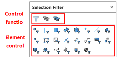
3)Click the highlighted element again to make it unhighlighted, and select Filters to automatically deactivate when none of the elements are highlighted.
4)Click the Control function icon in the toolbar to "Activate/Deactivate filters, Clear all types, Select all types."
Function description:
Filter rules:
- Do not start the command, only the elements belonging to the filter type can be picked up.
- Start any command, and the command is in the state to pick up a specific element (such as the stretch boss to pick up the sketch or to pick up the draw direction), if the specific element overlapped with the element set by the filter (such as the filter selected the axis), then only the overlapped element can be picked up (that is, only the axis can be selected, no other direction elements can be selected); If the specific element does not coincide with the element set by the filter (such as the filter selects the entity), the filter does not take effect (that is, any direction can be picked up elements).
- Start the measurement command to pick up only elements that belong to the filter type.
- Elements that are originally hidden or cannot be picked up due to occlusion can still not be picked up after "Select Filter" is set.
The filter toolbar can be hidden while the filter is activated, please note that the filter is still in effect at this time.
Default shortcut keys: F4- Explicit Select filter toolbar, F6- Activate/deactivate Select filter.
# Render Styles
Click  the icon to modify the model rendering style.
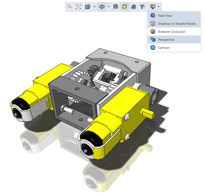
Note:Real View and Cartoon cannot be enabled at the same time.
# Capture
 This tool is only displayed in the sketch environment.
You can filter the points that need to be picked up and manipulated during the drawing process.
# Normal To Sketch Plane
 This tool is only displayed in the sketch environment. Quickly restore the view plane to face orientation.
# Rotate View
 This tool is displayed only in the Drawing environment. It allows rotating the orientation of the drawing view.
# Show Constraint Color
 This tool is displayed only in the Drawing environment. It allows switching the sketch color in the drawing to either constraint color or layer color.
# Show Hidden Element
 This tool is displayed only in the Drawing environment. It is used to set the visibility status of annotations.
# View Management
Quickly realize the view direction conversion, and can realize the rotation of the view, along the axis rotation, etc.

# Multiple Viewports

How to open:Click the "View Orientation" icon on the toolbar of the leading view or press the space bar to open the "View" dialog box. Select the number of viewports in the dialog box to open the multiple viewports.

Description:
- Under the multi-view interface, each view can be individually reoriented or rotated when the linked view is not open.
- When the linked view is open:
- The link icon is displayed in the view for differentiation, the non-orthogonal view is not in the linked state
- All orthogonal views are zooming and panning in an associated state, i.e. zooming or panning at the same time, at which point the view cannot be rotated through the mouse
- When you rotate the view out of the orthogonal direction via view orientation, the link state is automatically broken, and vice versa when you change the view to the orthogonal direction, the link state is automatically changed
- The link state can be turned off individually under each viewport
- Drag the divider bar to resize each viewport

Note:This function is not currently supported when editing parts in assembly
# Documents
View documents in your project, create new documents, search documents, Show parts, assembly, drawings, or all, sort by creation time, name, type, last edited time.
# List Display
Display all documents in the project as thumbnail + type + name. You can choose to sort by creation time, sort by name, sort by type. You can choose to display parts or assemblies.

# New document
Click  and create a new document, including parts, assembly, drawings, folders.

# Feature Management
Feature management includes two parts: feature panel and view panel.
# Feature Panel
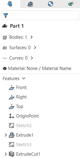
- Filter box: You can filter features by name.
- Part composition: solid, surface, curve. Foldable display.
- Part material: Right-click on the material, you can edit the part material; Double click "Material" to quickly open the Material library..
- Datum plane, origin: standard three datum plane - front, right, up.
- Feature list: Show sketch, feature from top down, can be suppressed or rolled back; Double click sketch to enter edit sketch, double click feature display driver size.
# View Panel
Contains a list of basic views, a list of custom views, and PMI, with an interface like the one below:

- Basic View: Right click on one of the views to display "Activate", "Orient View Only". "Activate" means that the viewport is currently positioned in this view, and smart dimensioning or labels are displayed in this view.
- Custom view: Record the view created through View Orientation or MBD-New view, right click on one of the views to display "Activate", "Orient View Only", "Rename", "Delete", "Show Associated PMI", "Hide Associated PMI". Views cannot be deleted when they are active.
- PMI: Displays smart sizes and labels that have been created under the current view.
# Graphic area
Display the graphics area where you can manipulate parts, assemblies, engineering drawings.
# Origin
The model origin is shown in black, representing the (0,0,0) coordinates of the model. When the sketch is activated, the point is shown in blue, representing the sketch's (0,0,0) coordinates.
Right-click provides shortcut keys such as "Show all", "Hide origin", "Adaptive", etc. Right-click at different positions to display different shortcut operations, as explained below.
# Right click on blank space
Right-click on any blank space in the viewport (without picking up any elements) to bring up a list of functions, as shown in the image below:

Show all:When there are elements in the hidden state, you can click Show all, then display all hidden elements.
Hide Origin: click to hide the origin of viewport coordinates, after hiding, you can also display the origin again.
Zoom to Fit:Adjust the enlarged or reduced viewport range to see the entire model.
Open Zoom to Area:After clicking this command, the box will select the area to zoom in, and the viewport will zoom in on the area.
Rotate:After clicking the rotation, the left mouse button of the viewport can control the rotation of the graph, and click to cancel the rotation will return to normal.
Pan:After clicking to pan, the left mouse button in the viewport can control the movement of the graphics, and clicking to cancel the pan will return to normal.
Open Drawing Document:Open the drawing of the current document.
Recent commands List:Record the last 3 operation commands in the current document, click to open the command again (This item is not displayed when the command operation is not executed).
# Right click on plane
Right-click on the datum plane to bring up a list of shortcut functions, as follows:
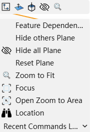
Floating box: Sketch, Normal to, Perpendicular To,Show/Hide, Zoom ro Fit.
Menu bar: Feature Dependency, Hide Other/all datum, Reset Plane, Zoom to Fit, Focus (zoom in on the current right-click feature), Open Zoom to Area (zoom in on the selected area),Location (in Feature Tree),Recent Command.
# Right click on part Bodies
Right-click on the part and a list of shortcut functions will pop up as follows:
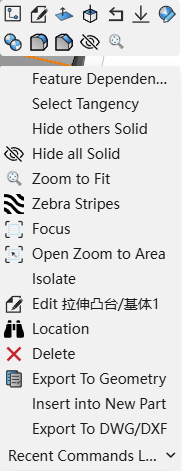
Floating box: Create Sketch, Edit features, Normal to, Perpendicular To , roll back, suppress, Set Appearance, Copy Appearance, Fillet,Chamfer,Show/Hide, Zoom to fit.
Menu bar: Feature Dependency,Select Tangency, Hide others Solid,Hide all Solid.Zoom to fit,Zebra Stripes,Focus,Open Zoom to Area ,Isolate,Edit features,Location,Delete,Export to geometry,Insert into New Part, Export to DWG/DXF, Recent commands.
# Right click on document name in Feature panel
Right-click on the document name at the top of the Features panel to bring up a list of shortcut features.
- Part Document

- Floating box: adaptive, transparent, set appearance, open engineering drawing.
- Menu bar: Material,Rename, Document properties, Custom properties, Collapse item.
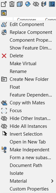
- Assemble Document

- Floating box: Adaptive, Hide all instances, transparent, Set appearance, Mate, open drawing.
- Menu bar: Insert new subassembly,Rename, , Document Attribute, Custom properties, Collapse item.
- Drawing Document

- Menu bar: Document properties, Rename, Custom properties, Collapse item, Rebuild.
# Right click on entity in feature panel
Right-click on the feature panel entity to bring up a list of shortcut functions.
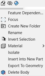
Floating box: Edit features, show/hide, set appearance.
Menu bar: Feature Dependency, Focus, Create new folder, Rename, Invert selection, Material,Isolate,Insert into New Part,Export to geometry,Delete body.
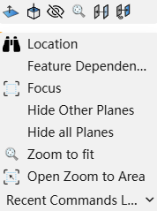
# Right click on the plane of the feature panel
Right-click on the datum of the feature panel to bring up a list of shortcut functions.

Floating box: Create Sketch, Normal toPerpendicular to, Show/Hide, Zoom to fit.
Menu bar: Feature Dependency,Rename, Focus, Hide the planes,Hide all planes,Reset plane, Invert selection.
# Right click on the sketch of feature panel
Right-click on the feature panel sketch to bring up a list of shortcut features.
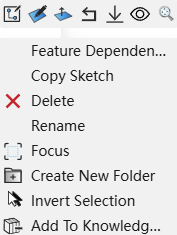
Floating box:Edit sketch, Edit sketch plane,Normal to , roll back, suppress, Show/Hide, Zoom to fit.
Menu bar:Feature Dependency,Copy Sketch, Delete, Rename, Focus, Create New folder, Invert selection, Add to Knowledge Base.
# Right click on the feature of feature panel
Right-click on a feature in the feature panel to bring up a list of shortcut functions.

Floating box: Edit feature, suppress, Zoom to fit.
Menu bar: Feature Dependency , Delete, rename, Invert selection.
# Right click on the assembly blank space
Right-click on any blank space in the assembly graphics area to bring up a list of its functions, as shown below:

- Hide Origin: Click to hide the origin of the world coordinates, after hiding, you can also display the origin again.
- Show all: When an instance, origin or datum is hidden, you can click Show All to display all hidden elements.
- Hide All: Click to hide all elements of the viewport instance, origin, datum, etc.
- Show Hidden Components: When an instance, origin or datum is hidden, click to display the hidden instance, origin or datum, and do not display those that are not previously hidden.
- Rotate: Click to rotate, the left mouse button in the viewport can control the rotation of the graph, click to cancel the rotation will return to normal.
- Pan: After clicking to pan, the left mouse button in the viewport can control the movement of the graphics, and clicking to cancel the pan will return to normal.
- Open Drawing Document: Open the drawing of the document.
- Open Zoom to Area: Select a region by dragging a box to zoom in and display the contents within that area.
- Recent Commands List: Displays the three most recent operating commands in the assembly document.
# Right click on the assembly viewport plane
In the assembly feature panel, right click on the datum surface to display the function list as follows:
# Right click on the assembly sub-parts
In the assembly, right-click the sub-part to display the function list as follows:
# Right click on the plane of the assembly feature list
In the assembly, right-click the datum surface in the feature list to display the function list as follows:

# Right click on the mates of assembly feature list
In the assembly, right-click the feature list to match the relationship and display the function list as follows:

For specific functions, refer to [Assembly] - [Instance list] - Right click function.
# Quick Confirmation
Provide quick confirmation function in multiple functions of sketch/parts/assembly/drawing.
Sketch:Use the "line, polygon, splin, intersection curve" command. When drawing, the right-click context menu displays the Exit option; clicking it exits the command.
Parts/Assembly/Drawing:When the mouse is operating in the viewport, you can quickly switch the next pick box or quickly create features.
- For commands that have multiple pick boxes, the mouse displays as when the pick completes the contents of one pick box
 .Right click at this point to switch to the next pick up box.
 - When the required elements of the feature are set and can be created, the mouse will display as
 .Click the right button to create the feature.
# TAB Pages
Display all open documents in the current project in a browser window, switching documents through the Documents TAB at the bottom of the page.
# Smart Shortcuts
In different scenarios, the corresponding menu content is displayed. There are four shortcut keys, namely "ESC", "Space", "S" and "D".
# Shortcut key "ESC"
The ESC key is used to exit the current command and cancel the pickup operation.
- Close the dialog box. Include: Project Settings (click project name within the document), branch, task, comment, Share, system Settings, each command dialog box (stretch, etc.), new dialog box (you can also close when you do not enter a name);
- ESC can not exit the sketch.
# Shortcut key "Space"
The space bar pops up view orientation bar: You can save the current camera view as a custom view at any time
For details, refer to 5 Modeling Interface View Direction.
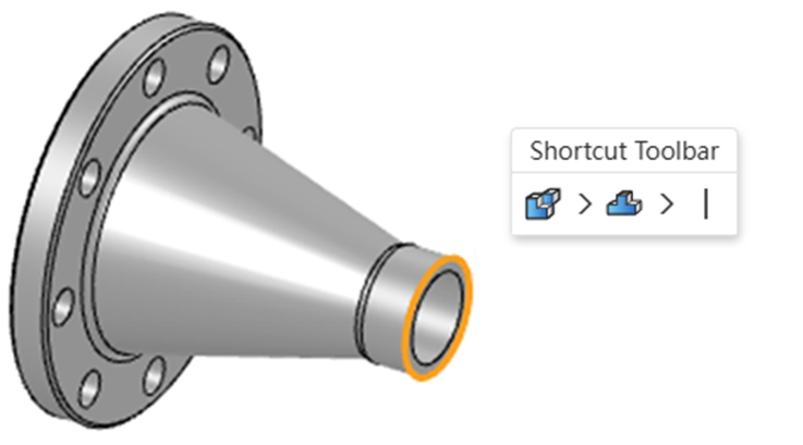
# Shortcut key "S"
Press the "S" key under Sketch, entity, Assembly scene to bring up the shortcut menu.
- The shortcut menu position appears preferentially in the lower right corner of the mouse.
- If there is insufficient space in the lower right corner of the mouse (for example, the mouse is located on the far right of the screen), the shortcut menu can be displayed in the lower left, upper left, and upper right of the mouse according to the actual situation. It should not exceed the screen and cause failure to click.
# Shortcut key "D"
Outside Sketch Mode (Part/Assembly): Select a single point, line, or face and press the D key. A panel displaying related elements will pop up, sequentially showing the parent elements of the selected item.
Inside Sketch Mode: Press the D key to display the Exit Sketch shortcut.